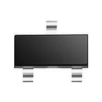
PMBFJ112 T/R NXP Semiconductors, PMBFJ112 T/R Datasheet - Page 2

PMBFJ112 T/R
Manufacturer Part Number
PMBFJ112 T/R
Description
RF JFET TAPE7 FET-RFSS
Manufacturer
NXP Semiconductors
Datasheet
1.PMBFJ112_TR.pdf
(8 pages)
Specifications of PMBFJ112 T/R
Configuration
Single
Mounting Style
SMD/SMT
Transistor Polarity
N-Channel
Drain Source Voltage Vds
40 V
Gate-source Breakdown Voltage
- 40 V
Maximum Drain Gate Voltage
- 40 V
Maximum Operating Temperature
+ 150 C
Package / Case
SOT-23
Lead Free Status / RoHS Status
Lead free / RoHS Compliant
Other names
PMBFJ112,215
Philips Semiconductors
3. Ordering information
4. Marking
5. Limiting values
6. Thermal characteristics
9397 750 13402
Product data sheet
Table 2:
Table 3:
[1]
Table 4:
In accordance with the Absolute Maximum Rating System (IEC 60134).
[1]
Table 5:
T
[1]
[2]
Type number
PMBFJ111
PMBFJ112
PMBFJ113
Type number
PMBFJ111
PMBFJ112
PMBFJ113
Symbol
V
V
V
I
P
T
T
Symbol
R
G
j
stg
j
DS
GSO
GDO
tot
th(j-a)
= P (R
* = p: Made in Hong Kong
* = t: Made in Malaysia
* = W: Made in China
Mounted on a ceramic substrate, 8 mm
Mounted on a ceramic substrate, 8 mm
Mounted on printed circuit board.
th(j-t)
Ordering information
Marking
Limiting values
Thermal characteristics
Parameter
thermal resistance from junction to ambient
thermal resistance from junction to ambient
+ R
Parameter
drain-source voltage (DC)
gate-source voltage
gate-drain voltage
forward gate current (DC)
total power dissipation
storage temperature
junction temperature
PMBFJ111; PMBFJ112; PMBFJ113
th(t-s)
Package
Name
-
+ R
Rev. 03 — 4 August 2004
th(s-a)
Description
plastic surface mounted package; 3 leads
) + T
amb
.
10 mm
10 mm
Conditions
T
amb
Marking code
41*
42*
47*
= 25 C
0.7 mm.
0.7 mm.
Conditions
[1]
© Koninklijke Philips Electronics N.V. 2004. All rights reserved.
[1]
Min
-
-
-
-
-
-
N-channel junction FETs
65
Max
50
300
+150
150
40
40
40
[1]
[2]
Typ
430
500
Unit
V
V
V
mA
mW
Version
SOT23
C
C
Unit
K/W
K/W
2 of 8


