S82Y-VM60D Omron, S82Y-VM60D Datasheet - Page 16
S82Y-VM60D
Manufacturer Part Number
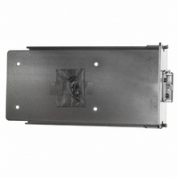
S82Y-VM60D
Description
DIN Rail Mtg Bkt K For 600 W
Manufacturer
Omron
Series
S8VMr
Specifications of S82Y-VM60D
Accessory Type
Mounting Bracket(s)
Lead Free Status / RoHS Status
Lead free / RoHS Compliant
For Use With/related Products
S8VM Series
Lead Free Status / Rohs Status
Lead free / RoHS Compliant
Other names
S82YVM60D
Z2814
Z2814


■ Remote Control Function
This function turns outputs ON and OFF using an external signal
while input voltage is applied, using the +RC pin (pin 7 on CN) and
the -RC pin (pin 8 on CN). Connect a switch or transistor to the +RC
and -RC pins to use the remote control function. When not using this
function, the +RC and -RC pins are shorted by using the standard
supplied connector.
Maximum input voltage: 12 V max.
Maximum allowable reverse voltage: − 1 V max.
Sink Current: 3.5 mA
Note: 1. Use 2-conductor shielded cable or twisted-pair cable as
■ Power Failure Alarm Function
The power failure alarm indicator will light red to indicate an output
voltage error if overload, overvoltage, or overheat protection is acti-
vated, if a drop in the input voltage causes the output voltage to drop,
if the built-in fan motor stops, and during remote control standby. The
alarm is also output externally by a transistor.
Transistor output: 30 VDC max., 50 mA max.
Residual voltage when ON: 2 V max.
Leakage current when OFF: 0.1 mA max.
Alarm detection voltage: Approx. 80% of output voltage setting
During detection, the transistor is OFF (with no continuity across pins
11 and 12 on CN), and the LED (red) lights.
Note: 1. This function monitors the voltage at the Power Supply out-
16
Short or L (0 to 0.8 V) ON
Open or H (2.4 to 12 V) OFF
+ RC Level for − RC
2. The remote control circuit is isolated from the input and out-
3. Remove the standard supplied connector and prepare a
2. Outputs are forced OFF if the built-in fan motor stops
3. Remove the standard supplied connector and prepare a
connection wire.
put circuits of the power supply.
connector separately.
put terminals. To check actual voltage, measure the voltage
on the load side.
(S8VM-15224C only).
connector separately.
Switch Mode Power Supply
S8VM
S8VM
CN
CN
Output
PF-C
PF-E
+RC
−RC
Vce max.: 30 VDC
Ic max.: 50 mA
SW
Rotate
Stop
Built-in Fan Motor
S8VM
TR
■ Inrush Current, Start Up Time,
■ Input Current Waveform When
(The following examples show typical waveforms.)
S8VM-300@@C
100 VAC, Load ratio: 100%
200 VAC, Load ratio: 100%
AC input
AC input
(10 A/DIV)
(10 A/DIV)
voltage
voltage
current
Output
AC input
AC input
AC input
AC input
voltage
voltage
voltage
voltage
current
current
Output
Output Hold Time
Input Is Turned ON
Output
Input ON
Inrush current on input application
100 ms
100 ms
Start up time
90%
Hold time
Input OFF
95%
Related parts for S82Y-VM60D
Image
Part Number
Description
Manufacturer
Datasheet
Request
R

Part Number:
Description:
TERMINAL COVER FOR S82J
Manufacturer:
Omron
Datasheet:
Part Number:
Description:
MOUNTNG BRKT SIDE FOR S8VM 15/30
Manufacturer:
Omron
Datasheet:
Part Number:
Description:
MOUNTNG BRAKT BOTTOM FOR S82H-30
Manufacturer:
Omron
Datasheet:
Part Number:
Description:
MOUNTNG BRAKT BOTTOM FOR S82H-50
Manufacturer:
Omron
Datasheet:
Part Number:
Description:
MNTNG BRKT SIDE FOR S8VM60/90/12
Manufacturer:
Omron
Datasheet:
Part Number:
Description:
MOUNTING BRAKT SIDE FOR S8VM 180
Manufacturer:
Omron
Datasheet:
Part Number:
Description:
MOUNTNG BRAKT FRONT FOR S82J-100
Manufacturer:
Omron
Datasheet:
Part Number:
Description:
MOUNTING BRAKT SIDE FOR S8VM 240
Manufacturer:
Omron
Datasheet:
Part Number:
Description:
DIN RAIL MNT BRACKET (25w/30w)
Manufacturer:
Omron
Datasheet:
Part Number:
Description:
S82D-300w PARAL.CONNECTION KIT
Manufacturer:
Omron
Datasheet:
Part Number:
Description:
S82D-300w BOTTOM BRACKET
Manufacturer:
Omron
Datasheet:
Part Number:
Description:
S82D-300w SIDE BRACKET
Manufacturer:
Omron
Datasheet:
Part Number:
Description:
S82D-600w BOTTOM BRACKET
Manufacturer:
Omron
Datasheet:
Part Number:
Description:
S82D-600w SIDE BRACKET
Manufacturer:
Omron
Datasheet:
Part Number:
Description:
S82D FAN
Manufacturer:
Omron
Datasheet: