S82Y-VM60D Omron, S82Y-VM60D Datasheet - Page 34
S82Y-VM60D
Manufacturer Part Number
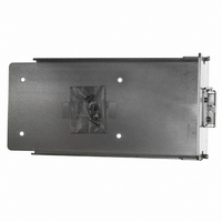
S82Y-VM60D
Description
DIN Rail Mtg Bkt K For 600 W
Manufacturer
Omron
Series
S8VMr
Specifications of S82Y-VM60D
Accessory Type
Mounting Bracket(s)
Lead Free Status / RoHS Status
Lead free / RoHS Compliant
For Use With/related Products
S8VM Series
Lead Free Status / Rohs Status
Lead free / RoHS Compliant
Other names
S82YVM60D
Z2814
Z2814


Insulation Test
When performing the test, be sure to short-circuit all the output
terminals to protect them from damage.
Inrush Current
When two or more Power Supplies are connected to the same input,
inrush current is added to the total current. Select fuses and circuit
breakers giving sufficient consideration to the fusing or operating
characteristics so that fuses will not burn and breakers will not break
due to inrush current.
Output Voltage Adjuster (V.ADJ)
Default Setting: Set at the rated voltage
Adjustable Range: Adjustable with output voltage adjuster (V.ADJ) on
the front panel of the Power Supply from − 20% to 20% of the rated
output voltage ( − 10% to 20% of the rated voltage for S8VM-
@@@24A@/P@)
Turning clockwise increases the output voltage and turning
counterclockwise decreases the output voltage.
The output voltage adjuster (V.ADJ) may possibly be damaged if it is
turned with unnecessary force. Do not turn the adjuster with
excessive force.
After completing output voltage adjustment, be sure that the output
capacity or output current does not exceed the rated output capacity
or rated output current.
The output voltage may increase beyond the allowable voltage range
(up to +20% of the rated voltage) depending on the operation of the
output voltage adjuster (V.ADJ). When adjusting the output voltage,
check the output voltage of the Power Supply and be sure that the
load is not damaged.
When increasing the output voltage to more than +20% of the rated
value using the output voltage adjuster (V. ADJ), the overvoltage
protection function may operate.
(S8VM-@@@24A@/P@ Only)
Turn the output voltage adjuster (V.ADJ) slowly. When decreasing the
output voltage quickly, or when adjusting the output voltage to less
than − 10% of the rated value, the undervoltage alarm function may
operate.
Ripple
(S8VM-15224C Only)
The rated ripple noise voltage was measured using a measuring cir-
cuit that conforms to the JEITA standard RC-9131A.
Remote Sensing Function
100/150-W Models
If the + S and − S terminals are opened by removing the short bar, the
overvoltage protection function will be activated and the output volt-
age will be cut off.
300/600/1,500-W Models
The stability and accuracy of the output will deteriorate if the + S or −
S pins are open. Always connect the + S and − S pins.
34
+V +S −V −S
S8VM
CN
Switch Mode Power Supply
+V
−V
C1
+
C2
R: 50 Ω
C1: 4700 pF
C2: 22 uF
C3: 0.47 uF
Coaxial cable
1.5 m 50 Ω
Load
C3
R
S8VM
Frequency band
100 MHz
Oscilloscope
Series Operation
Two Power Supplies can be connected in series.
The ( ± ) voltage output can be accomplished with two Power Sup-
plies.
Series Operation
Note: 1. If the load is short-circuited, a reverse voltage may be ap-
Parallel Operation
15/30/50/100/150-W Models
The Power Supply is not designed for parallel operation.
300/600/1,500-W Models
If the CB pin (pin 5 on CN) and the CBG pin (pin 6 on CN) are con-
nected, the current balance function will operate and parallel opera-
tion will be possible at 80% or less of the total output capacity.
Up to 2 Power Supplies can be connected.
15W/30W
Correct
Output Voltage ( ± )
Correct
Incorrect
2. Though Power Supplies having different specifications can
AC (N)
AC (N)
AC (L)
AC (L)
AC (N)
AC (N)
AC (L)
AC (L)
plied inside the Power Supply unit, and this may possibly
cause the deterioration or damage of the Power Supply unit.
Connect the diode as shown in the figure. Use the following
guidelines to select the diode to be connected.
be connected in series, the current flowing through the load
must not exceed the smaller rated output current.
Dielectric strength
(V
Forward current (I
RRM
)
Type
+V
−V
+V
−V
+V
−V
+V
−V
AC (N)
AC (N)
AC (L)
AC (L)
F
) Twice the rated output current or
Twice the rated output voltage or
above
above
50W/100W/150W/300W/600W/
1,500W
Correct
Schottky Barrier diode
AC (N)
AC (N)
AC (L)
AC (L)
+V
−V
+V
−V
+V
−V
+V
−V
Related parts for S82Y-VM60D
Image
Part Number
Description
Manufacturer
Datasheet
Request
R

Part Number:
Description:
TERMINAL COVER FOR S82J
Manufacturer:
Omron
Datasheet:
Part Number:
Description:
MOUNTNG BRKT SIDE FOR S8VM 15/30
Manufacturer:
Omron
Datasheet:
Part Number:
Description:
MOUNTNG BRAKT BOTTOM FOR S82H-30
Manufacturer:
Omron
Datasheet:
Part Number:
Description:
MOUNTNG BRAKT BOTTOM FOR S82H-50
Manufacturer:
Omron
Datasheet:
Part Number:
Description:
MNTNG BRKT SIDE FOR S8VM60/90/12
Manufacturer:
Omron
Datasheet:
Part Number:
Description:
MOUNTING BRAKT SIDE FOR S8VM 180
Manufacturer:
Omron
Datasheet:
Part Number:
Description:
MOUNTNG BRAKT FRONT FOR S82J-100
Manufacturer:
Omron
Datasheet:
Part Number:
Description:
MOUNTING BRAKT SIDE FOR S8VM 240
Manufacturer:
Omron
Datasheet:
Part Number:
Description:
DIN RAIL MNT BRACKET (25w/30w)
Manufacturer:
Omron
Datasheet:
Part Number:
Description:
S82D-300w PARAL.CONNECTION KIT
Manufacturer:
Omron
Datasheet:
Part Number:
Description:
S82D-300w BOTTOM BRACKET
Manufacturer:
Omron
Datasheet:
Part Number:
Description:
S82D-300w SIDE BRACKET
Manufacturer:
Omron
Datasheet:
Part Number:
Description:
S82D-600w BOTTOM BRACKET
Manufacturer:
Omron
Datasheet:
Part Number:
Description:
S82D-600w SIDE BRACKET
Manufacturer:
Omron
Datasheet:
Part Number:
Description:
S82D FAN
Manufacturer:
Omron
Datasheet: