S82Y-VM60D Omron, S82Y-VM60D Datasheet - Page 33
S82Y-VM60D
Manufacturer Part Number
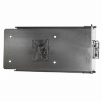
S82Y-VM60D
Description
DIN Rail Mtg Bkt K For 600 W
Manufacturer
Omron
Series
S8VMr
Specifications of S82Y-VM60D
Accessory Type
Mounting Bracket(s)
Lead Free Status / RoHS Status
Lead free / RoHS Compliant
For Use With/related Products
S8VM Series
Lead Free Status / Rohs Status
Lead free / RoHS Compliant
Other names
S82YVM60D
Z2814
Z2814


Recommended Wire Sizes
The current rating for the output terminals on the S8VM-300@@C is
40 A per terminal. The current rating for the output terminals on the
S8VM-600@@C is 60 A per terminal. Use two terminals together if a
current exceeding the terminal rating is used.
Use min. 60°C or 60/75°C wire.
Use copper conductors only.
Undervoltage Alarm Output Connector
Harness Manufacture Method
The following products are provided with the S8VM-05024A@/P@,
S8VM-10024A@/P@ and S8VM-15024A@/P@ for the undervoltage
alarm transistor output wiring.
Be sure to prepare the connector according to the following instruc-
tions to ensure correct wiring. For details, refer to the JST catalog.
• Use a wire size of AWG28 to AWG22.
• The guideline for the length of sheath to be stripped from the wire is
• Use either a YC or YRS Crimping Tool (manufactured by JST) to
• Be sure to insert the crimped terminal wires into the housing fully
Signal I/O Connector Harness
Manufacture Method
The S8VM-300@@C/600@@C/15224C are using PHD connector
(manufactured by JST).
Be sure to prepare the connector according to the following instruc-
tions to ensure correct wiring. For details, refer to the JST catalog.
• Use a wire size of AWG26 to AWG22.
• The guideline for the length of sheath to be stripped from the wire is
Input
Output
Connector
Housing (provided) XHP-3
Terminal (provided) BXH-001T-P0.6 or SXH-001T-P0.6
Connector
Housing
Terminal
2.1 to 2.6 mm.
crimp the terminal and wire.
until a click is heard. Also, make sure that the wires attached to the
housing are securely locked in place.
2.3 mm.
Terminal
S8VM-015@@@@
S8VM-030@@@@
S8VM-050@@@@
S8VM-100@@@@
S8VM-150@@@@
S8VM-300@@C
S8VM-600@@C
S8VM-15224C
S8VM-015@@@@
S8VM-030@@@
S8VM-050@@@@
S8VM-100@@@@
S8VM-150@@@@
S8VM-300@@C
S8VM-600@@C
S8VM-15224C
S8VM-300@@C/600@@C/15224C
S12B-PHDSS
PHDR-12VS
SPHD-001T-P0.5 or BPHD-001T-P0.5
S8VM-
05024A@/P@
S3B-XH-A-1
Model
(M3.5)
(M4)
(M3.5)
(M4)
(M4)
(M5)
(M8
bolts and
nuts)
S8VM-10024A@/P@ Manu-
S8VM-15024A@/P@
BH3B-XH-2
AWG24 to AWG14
(0.205 to 2.081 mm
AWG20 to AWG10
(0.52 to 5.27 mm
AWG24 to AWG14
(0.205 to 2.081 mm
AWG24 to AWG12
(0.205 to 3.309 mm
AWG16 to AWG10
(1.32 to 5.27 mm
AWG14 to AWG8
(2.08 to 8.3 mm
AWG8 to AWG4
(8.3 to 21.09 mm
Recommended wire size
2
)
2
2
2
)
)
)
Manu-
factured
by JST
factured
by JST
2
2
2
)
)
)
• Use a YC Crimping Tool (manufactured by JST) to crimp the termi-
• Applicable wire per barrel size is UL1007 (standard wire) and its
• Be sure to insert the crimped terminal wires into the housing fully
Installation Environment
Do not use the Power Supply in locations subject to shocks or
vibrations. In particular, install the Power Supply as far away as
possible from contactors or other devices that are a vibration source.
Install the Power Supply well away from any sources of strong, high-
frequency noise and surge.
Operating Life
The life of a Power Supply is determined by the life of the electrolytic
capacitors used inside. Here, Arrhenius Law applies, i.e., the life will
be halved for each rise of 10 ° C or the life will be doubled for each
drop of 10 ° C. The life of the Power Supply can thus be increased by
reducing its internal temperature.
Ambient Operating and Storage
Environments
Store the Power Supply at a temperature of − 25 to 65°C and a
humidity of 25% to 90%.
The Internal parts may occasionally be deteriorated or damaged.
Do not use the Power Supply outside the derating range (i.e., under
conditions indicated by the shaded area (
curve diagrams on pages 9 and 15.)
Use the Power Supply at a humidity of 30% to 85%.
Do not use the Power Supply in locations subject to direct sunlight.
Do not use the Power Supply in locations where liquids, foreign
matter, or corrosive gases may enter the interior of the Power Supply.
Overcurrent Protection
Internal parts may occasionally deteriorate or be damaged if a short-
circuited or other overcurrent state continues during operation.
Eliminate the overcurrent state as soon as possible.
Internal parts may possibly be deteriorated or damaged if the Power
Supply is used for applications with frequent inrush current or
overloading at the load end. Do not use the Power Supply for such
applications.
Charging the Battery
If a battery is to be connected as the load, install an overcurrent
limiting circuit and an overvoltage protection circuit.
Dielectric Strength Test
If a high voltage is applied between an input and the case (PE/FG), it
will pass though the LC of the built-in noise filter and energy will be
stored. If the high voltages used for dielectric strength testing are
turned ON and OFF with a switch, timer, or similar device, impulse
voltage will be generated when the voltage is turned OFF and
internal parts may possibly be damaged. To prevent the generation
of impulse voltages, reduce the applied voltage slowly with a variable
resistor on the test device or turn the voltage ON and OFF at the
zero-cross point.
When performing the test, be sure to short-circuit all the output
terminals to protect them from damage.
Check the waveform of the applied voltage while testing. High
voltage due to distortions of the applied voltage may be produced
depending on the type of testing equipment.
nal and wire.
equivalent standard wire can be used. Use UL1061 or its equiva-
lent standard wire for AWG22 wires, because the wire insulation
outer diameter of UL1061 is small.
until a click is heard. Also, make sure that the wires attached to the
housing are securely locked in place.
Switch Mode Power Supply
S8VM
) in the derating
33
Related parts for S82Y-VM60D
Image
Part Number
Description
Manufacturer
Datasheet
Request
R

Part Number:
Description:
TERMINAL COVER FOR S82J
Manufacturer:
Omron
Datasheet:
Part Number:
Description:
MOUNTNG BRKT SIDE FOR S8VM 15/30
Manufacturer:
Omron
Datasheet:
Part Number:
Description:
MOUNTNG BRAKT BOTTOM FOR S82H-30
Manufacturer:
Omron
Datasheet:
Part Number:
Description:
MOUNTNG BRAKT BOTTOM FOR S82H-50
Manufacturer:
Omron
Datasheet:
Part Number:
Description:
MNTNG BRKT SIDE FOR S8VM60/90/12
Manufacturer:
Omron
Datasheet:
Part Number:
Description:
MOUNTING BRAKT SIDE FOR S8VM 180
Manufacturer:
Omron
Datasheet:
Part Number:
Description:
MOUNTNG BRAKT FRONT FOR S82J-100
Manufacturer:
Omron
Datasheet:
Part Number:
Description:
MOUNTING BRAKT SIDE FOR S8VM 240
Manufacturer:
Omron
Datasheet:
Part Number:
Description:
DIN RAIL MNT BRACKET (25w/30w)
Manufacturer:
Omron
Datasheet:
Part Number:
Description:
S82D-300w PARAL.CONNECTION KIT
Manufacturer:
Omron
Datasheet:
Part Number:
Description:
S82D-300w BOTTOM BRACKET
Manufacturer:
Omron
Datasheet:
Part Number:
Description:
S82D-300w SIDE BRACKET
Manufacturer:
Omron
Datasheet:
Part Number:
Description:
S82D-600w BOTTOM BRACKET
Manufacturer:
Omron
Datasheet:
Part Number:
Description:
S82D-600w SIDE BRACKET
Manufacturer:
Omron
Datasheet:
Part Number:
Description:
S82D FAN
Manufacturer:
Omron
Datasheet: