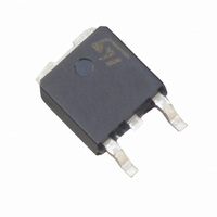
BYW4200B-TR STMicroelectronics, BYW4200B-TR Datasheet

BYW4200B-TR
Specifications of BYW4200B-TR
Available stocks
Related parts for BYW4200B-TR
BYW4200B-TR Summary of contents
Page 1
... FSM Tstg Storage temperature range Tj Maximum operating junction temperature October 1999 - Ed 200 V 0. 150 °C 4 DPAK BYW4200B Parameter DPAK Tcase = 130°C SMC Tlead = 70° sinusoidal SMBYW04-200 BYW4200B 2 4 (TAB 1(nc) SMC (JEDEC DO-214AB) SMBYW04-200 Value Unit 200 150 C 150 °C ...
Page 2
... SMBYW04-200 / BYW4200B THERMAL RESISTANCE Symbol Parameter R Junction to case th (j-c) R Junction to leads th (j-l) STATIC ELECTRICAL CHARACTERISTICS Symbol Tests Conditions I * Reverse leakage current Forward voltage drop F Pulse test : * ms, < 380 s, < evaluate the maximum conduction losses use the following equation : 0 0.037 I F(AV) F (RMS) ...
Page 3
... Ta=25° Ta=50° 1E-3 1E-1 1E+0 Fig. 6-2: Variation of thermal impedance junction to case versus pulse duration (BYW4200B). Zth(j-c)/Rth(j-c) 1.0 = 0.5 0.5 = 0.2 = 0.1 0.2 T Single pulse =tp/T tp 0.1 1E+2 5E+2 1E-3 SMBYW04-200 / BYW4200B Tj=100°C (Typical values) Tj=25°C Tj=100° ...
Page 4
... SMBYW04-200 / BYW4200B Fig. 7: Reverse recovery current versus dI IRM(A) 2.5 IF=IF(av) 90% confidence 2.0 1.5 1.0 0.5 0 Fig. 9: Junction capacitance versus reverse voltage applied (typical values). C(pF) 100 50 20 VR( Fig. 11-1: Thermal resistance junction to ambient versus copper surface under each lead (Epoxy printed circuit board FR4, copper thickness: 35mm) (SMBYW04-200). Rth(j-a) (° ...
Page 5
... PACKAGE MECHANICAL DATA DPAK FOOT PRINT (in millimeters) 6.7 1.6 2.3 2.3 REF 6 1.6 SMBYW04-200 / BYW4200B DIMENSIONS Millimeters Inches Min. Max Min. Max. 2.20 2.40 0.086 0.094 0.90 1.10 0.035 0.043 0.03 0.23 0.001 0.009 0.64 0.90 0.025 0.035 5.20 5.40 0.204 ...
Page 6
... SMBYW04-200 / BYW4200B PACKAGE MECHANICAL DATA SMC FOOT PRINT (in millimeters) 2.0 4.2 Ordering code Marking SMBYW04-200 D20 BYW4200B W4200 BYW4200B-RL W4200 Epoxy meets UL 94,V0 Band indicates cathode Information furnished is believed to be accurate and reliable. However, STMicroelectronics assumes no responsibility for the consequences of use of such information nor for any infringement of patents or other rights of third parties which may result from its use. No license is granted by implication or otherwise under any patent or patent rights of STMicroelectronics ...


