IRGB10B60KDPBF International Rectifier, IRGB10B60KDPBF Datasheet - Page 2
IRGB10B60KDPBF
Manufacturer Part Number
IRGB10B60KDPBF
Description
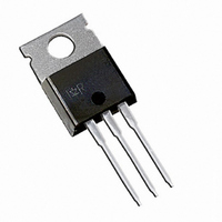
IGBT W/DIODE 600V 22A TO-220AB
Manufacturer
International Rectifier
Type
Ultrafastr
Datasheets
1.IRGSL10B60KDPBF.pdf
(16 pages)
2.IRGB10B60KDPBF.pdf
(3 pages)
3.IRGB10B60KDPBF.pdf
(15 pages)
Specifications of IRGB10B60KDPBF
Igbt Type
NPT
Voltage - Collector Emitter Breakdown (max)
600V
Vce(on) (max) @ Vge, Ic
2.2V @ 15V, 10A
Current - Collector (ic) (max)
22A
Power - Max
156W
Input Type
Standard
Mounting Type
Through Hole
Package / Case
TO-220-3 (Straight Leads)
Capacitance, Gate
620 pF
Current, Collector
22 A
Energy Rating
390 μJ
Package Type
TO-220AB
Polarity
N-Channel
Power Dissipation
156 W
Resistance, Thermal, Junction To Case
0.8 °C/W
Speed, Switching
10 to 30 kHz
Voltage, Collector To Emitter Shorted
600 V
Voltage, Collector To Emitter, Saturation
1.8 V
Transistor Type
IGBT
Dc Collector Current
22A
Collector Emitter Voltage Vces
2.2V
Power Dissipation Pd
104W
Collector Emitter Voltage V(br)ceo
600V
Operating Temperature Range
-55°C To +150°C
Rohs Compliant
Yes
Lead Free Status / RoHS Status
Lead free / RoHS Compliant
Other names
*IRGB10B60KDPBF
Available stocks
Company
Part Number
Manufacturer
Quantity
Price


IRG/B/S/SL10B60KDPbF
Electrical Characteristics @ T
Switching Characteristics @ T
Note
RBSOA
SCSOA
Qg
Qge
Qgc
E
E
E
t
t
t
t
E
E
E
t
t
t
t
C
C
C
Erec
t
I
V
∆V
V
V
∆
g
I
V
I
CES
GES
d(on)
r
d(off)
f
d(on)
r
d(off)
f
rr
rr
V
fe
on
off
tot
on
off
tot
(BR)CES
CE(on)
GE(th)
FM
ies
oes
res
2
(BR)CES
GE(th)
/
∆
/∆T
T
to
J
J
Total Gate Charge (turn-on)
Gate - Emitter Charge (turn-on)
Gate - Collector Charge (turn-on)
Turn-On Switching Loss
Turn-Off Switching Loss
Total Switching Loss
Turn-On Delay Time
Rise Time
Turn-Off Delay Time
Fall Time
Turn-On Switching Loss
Turn-Off Switching Loss
Total Switching Loss
Turn-On Delay Time
Rise Time
Turn-Off Delay Time
Fall Time
Input Capacitance
Output Capacitance
Reverse Transfer Capacitance
Reverse Recovery energy of the diode
Diode Reverse Recovery time
Diode Peak Reverse Recovery Current
Collector-to-Emitter Breakdown Voltage
Temperature Coeff. of Breakdown Voltage
Collector-to-Emitter Saturation Voltage
Gate Threshold Voltage
Temperature Coeff. of Threshold Voltage –––
Forward Transconductance
Zero Gate Voltage Collector Current
Diode Forward Voltage Drop
Gate-to-Emitter Leakage Current
Reverse Bias Safe Operting Area
Short Circuit Safe Operting Area
„
are on page 15
Parameter
Parameter
J
J
= 25°C (unless otherwise specified)
= 25°C (unless otherwise specified)
Min. Typ. Max. Units
Min. Typ. Max. Units
–––
–––
––– 16.3
–––
–––
–––
–––
–––
–––
–––
–––
–––
–––
–––
–––
–––
–––
–––
–––
–––
–––
–––
–––
600
–––
––– 2.20 2.50
–––
–––
–––
––– 1.30 1.45
–––
––– 1.30 1.45
1.5
3.5
10
FULL SQUARE
1.80 2.20
140
250
390
230
230
350
580
250
620
245
–––
300
––– ±100
4.3
0.3
4.5
-10
7.0
3.0
–––
38
30
20
23
30
20
26
62
22
90
19
–––
–––
–––
247
360
607
262
340
464
804
274
–––
–––
–––
330
105
–––
–––
––– mV/°C V
–––
150
700
5.5
–––
39
29
32
39
28
34
22
V/°C
µA
nA
nC
µJ
ns
µJ
ns
pF
µs
µJ
ns
V
V
V
S
V
A
I
V
V
I
V
Ls = 150nH
I
V
Ls = 150nH, T
I
V
Ls = 150nH
I
V
Ls = 150nH, T
V
V
f = 1.0MHz
T
V
T
V
T
V
V
V
V
I
I
V
V
V
V
I
I
V
C
C
C
C
C
C
C
C
C
J
CC
J
J
CC
GE
GE
GE
GE
GE
GE
CC
CC
CC
GE
GE
GE
CE
CE
CE
GE
GE
GE
= 10A
= 10A, V
= 10A, V
= 10A, V
= 10A, V
= 10A, V
= 10A, V
= 10A
= 10A
= 150°C
= 150°C, I
= 150°C, Vp =600V,R
= 500V, V
= 400V
= 15V
= 15V,R
= 15V, R
= 15V,R
= 15V, R
= 0V
= 30V
= 360V, V
= 400V, I
= 15V,R
= 0V, I
= 0V, I
= V
= V
= 50V, I
= 0V, V
= 0V, V
= ±20V
GE
GE
, I
, I
C
CC
CC
CC
CC
C
GE
GE
CE
CE
C
C
C
Conditions
G
G
G
Conditions
C
= 500µA
= 1.0mA, (25°C-150°C)
T
G
G
GE
F
J
J
= 250µA
= 1.0mA, (25°C-150°C)
= 400V
= 400V
= 400V
= 400V
= 15V
= 15V
= 10A, PW=80µs
J
= 47Ω, L = 200µH
= 47Ω, L = 200µH
GE
= 47Ω, Ls = 150nH
= 44A, Vp =600V
= 600V
= 600V, T
= 47Ω, L = 200µH
= 47Ω, L = 200µH
= 10A, L = 200µH
= 25°C
= 150°C
= 150°C
= +15V to 0V,
= +15V to 0V
T
T
www.irf.com
J
J
= 25°C ƒ
= 150°C ƒ
G
T
J
J
= 150°C
= 47Ω
= 150°C
R
G
= 47Ω
CT4,WF3
5, 6,7
9,10,11
9,10,11
12
17,18,19
Ref.Fig.
20, 21
WF1WF2
Ref.Fig.
13,15
14, 16
WF4
CT4
CT4
CT3
CT1
WF1
WF2
CT2
8
CT4
CT4
4
Related parts for IRGB10B60KDPBF
Image
Part Number
Description
Manufacturer
Datasheet
Request
R

Part Number:
Description:
SCHOTTKY RECTIFIER
Manufacturer:
International Rectifier Corp.
Datasheet:
Part Number:
Description:
SCHOTTKY RECTIFIER
Manufacturer:
International Rectifier Corp.
Datasheet:
Part Number:
Description:
SCHOTTKY RECTIFIER
Manufacturer:
International Rectifier Corp.
Datasheet:
Part Number:
Description:
SCHOTTKY RECTIFIER
Manufacturer:
International Rectifier Corp.
Datasheet:
Part Number:
Description:
SCHOTTKY RECTIFIER
Manufacturer:
International Rectifier Corp.
Datasheet:
Part Number:
Description:
SCHOTTKY RECTIFIER
Manufacturer:
International Rectifier Corp.
Datasheet:
Part Number:
Description:
SCHOTTKY RECTIFIER
Manufacturer:
International Rectifier Corp.
Datasheet:
Part Number:
Description:
SCHOTTKY RECTIFIER
Manufacturer:
International Rectifier Corp.
Datasheet:
Part Number:
Description:
SCHOTTKY RECTIFIER
Manufacturer:
International Rectifier Corp.
Datasheet:
Part Number:
Description:
SCHOTTKY RECTIFIER
Manufacturer:
International Rectifier Corp.
Datasheet:
Part Number:
Description:
SCHOTTKY RECTIFIER
Manufacturer:
International Rectifier Corp.
Datasheet:
Part Number:
Description:
SCHOTTKY RECTIFIER
Manufacturer:
International Rectifier Corp.
Datasheet:
Part Number:
Description:
SCHOTTKY RECTIFIER
Manufacturer:
International Rectifier Corp.
Datasheet:
Part Number:
Description:
SCHOTTKY RECTIFIER
Manufacturer:
International Rectifier Corp.
Datasheet:
Part Number:
Description:
SCHOTTKY RECTIFIER
Manufacturer:
International Rectifier Corp.
Datasheet: