350199-1 TE Connectivity, 350199-1 Datasheet - Page 40
350199-1
Manufacturer Part Number
350199-1
Description
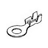
RING 18-14 10 020 NIPST
Manufacturer
TE Connectivity
Type
Ring Tongue Terminalr
Datasheet
1.350199-1.pdf
(76 pages)
Specifications of 350199-1
Stud Size
10mm
Wire Gauge
14-18
Body Plating
Nickel
Body Material
Steel
Insulation
Non-Insulated
Product Depth (mm)
8.69mm
Product Length (mm)
19.89mm
Color
Not Required
Rohs Compliant
YES
Terminal Shape
Ring Tongue
Receptacle Style
Straight
Barrel Type
Open Barrel
Wire/cable Type
Regular Wire
Insulation Support
Insulation Support
Insulation Diameter (mm [in])
3.05-4.45 [.120-.175]
Stud Diameter (mm [in])
4.82 [0.190]
Shape
RING-001
Heavy Duty
No
Finish
Nickel
Wire Range (mm [awg])
0.80-2.00² [18-14]
Stock Thickness (mm [in])
0.51 [0.020]
Government/industry Qualification
No
Rohs/elv Compliance
RoHS compliant, ELV compliant
Lead Free Solder Processes
Not relevant for lead free process
Rohs/elv Compliance History
Always was RoHS compliant
Packaging Method
Strip
Lead Free Status / RoHS Status
Compliant
Available stocks
Company
Part Number
Manufacturer
Quantity
Price
Company:

Part Number:
350199-1
Manufacturer:
TE
Quantity:
20 000


40
MTM Crimpband
Interconnection System
How the System Operates
➀
➁
➂
➃
➄
Connector Specification Code
Splice No.
Example:
Legend
* Customer has their own Tooling
Catalog 82227
Revised 8-04
www.tycoelectronics.com
Leased
Machine
Feed (Magnet Wire
Connector Material)
Machine feeds strip until
the strip hits the wire stop.
Shear (Blank Length)
The strip is cut by the
cutter block former bar
insert tooling.
Bend (Crimp Formed)
The former bar drives the
cut strip over the anvil,
bending the cut strip into
an upside down “U”.
Wire (Placement)
In Pigtail and Parallel
(Thru) splices magnet
wires must be placed on
top of the lead wire.
Crimp (Crimp Formed)
The anvil retracts as the
driver takes the formed
strip down into the
clincher.
Basis
L
L
Machine Basis
Purchase
B.L. Dim.
Tooling
L
Size
P
092
092
See Figure 1 and/or Legend below
General
Connector
Dimensions are in inches and
millimeters unless otherwise
specified. Values in brackets
are metric equivalents.
W Dim.
G*
Width
6R
6R
Machine Applied Terminations, Open Barrel Terminals
(Rings, Spades, Pins, Receptacles, Splices, Tabs)
MTM Crimpband Splices
Note: For B/L above, .546 consult
Tyco Electronics for tooling size
code.
Thickness
Material
T Dim.
20
Size Code
Tooling
032/036
061/076
076/092
092/125
125/160
125/165
20
032
036
045
051
061
076
092
125
165
T
Finish
T
Blank Length
B/L (Nom.)
B
Dimensions are shown for
reference purposes only.
Specifications subject
to change.
.167
.228
.224
.246
.267
.292
.324
.339
.361
.379
.413
.446
.485
.506
.546
Material
Code
B
A
(Continued)
Notes: So that the proper Crimpband splice is chosen, Tyco Electronics
Thickness
Connector Width Code
Material
Material
10R
4R
6R
8R
Code
Code
TB
12
14
16
20
25
B
A
recommends the following:
1. Submit 10 samples of wire combinations and/or components to be
2. Pull-out force and/or millivolt drop tests will be performed to
3. Tooling and testing will be documented on a Material & Tooling
4. Crimpband material quotes, tooling quotes and samples will be
➀
Magnet Wires
on top
crimped with any special requirements to your Tyco Electronics
sales representative.
develop recommendations for proper Crimpband material, toolset
and crimp heights.
Sheet (M & T sheet).
submitted to the customer.
USA: 1-800-522-6752
Canada: 1-905-470-4425
Mexico: 01-800-733-8926
C. America: 52-55-5-729-0425
A
11 Serrations
Lead Wire
5 Serrations
7 Serrations
9 Serrations
CDA 725 Copper/
T±.002
Material/Finish
CDA 260 Brass
CDA 260 Brass
Dim.
.012
.014
.016
.020
.025
Pre-Tin over
Nickel Alloy
Serration
➄
Depth
➂
T
.005
.005
.007
.007
.007
➃
➁
D
.138
.154
.194
.234
W
Burrs
Section A-A
Wire Size Force Requirements
Length
AWG
Blank
South America: 55-11-3611-1514
Hong Kong: 852-2735-1628
Japan: 81-44-844-8013
UK: 44-141-810-8967
W
26
24
22
20
18
16
14
12
10
W
Serrations
UL486C Pull Out
Laboratory (lbs.)
Underwriters
10
10
15
25
35
40
3
5
8
D
Related parts for 350199-1
Image
Part Number
Description
Manufacturer
Datasheet
Request
R

Part Number:
Description:
Printers THERMAL PRINTER HS-SLEEVE MARKER
Manufacturer:
TE Connectivity


Part Number:
Description:
High Speed / Modular Connectors 30P HEADER ASSY
Manufacturer:
TE Connectivity
Datasheet:

Part Number:
Description:
High Speed / Modular Connectors REC 6X005P R/A LT B-PLANE HS3
Manufacturer:
TE Connectivity
Datasheet:

Part Number:
Description:
High Speed / Modular Connectors 2MM HM RCPT 50P R/A AU
Manufacturer:
TE Connectivity
Datasheet:

Part Number:
Description:
High Speed / Modular Connectors 2MM HM RCPT 50P R/A AU
Manufacturer:
TE Connectivity
Datasheet:


Part Number:
Description:
Manufacturer:
TE Connectivity
Datasheet:


Part Number:
Description:
Manufacturer:
TE Connectivity
Datasheet:

Part Number:
Description:
Manufacturer:
TE Connectivity
Datasheet:

Part Number:
Description:
Manufacturer:
TE Connectivity
Datasheet: