PD84002 STMicroelectronics, PD84002 Datasheet - Page 12
PD84002
Manufacturer Part Number
PD84002
Description
TRANS RF POWER LDMOST
Manufacturer
STMicroelectronics
Datasheet
1.PD84002.pdf
(16 pages)
Specifications of PD84002
Transistor Type
LDMOS
Frequency
870MHz
Gain
15dB
Voltage - Rated
25V
Current Rating
2A
Current - Test
100mA
Voltage - Test
7.5V
Power - Output
2W
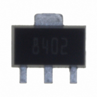
Package / Case
SOT-89
Drain Source Voltage Vds
25V
Continuous Drain Current Id
2A
Power Dissipation Pd
6W
Operating Temperature Range
-65°C To +150°C
Rf Transistor Case
SOT-89
Configuration
Single
Transistor Polarity
N-Channel
Drain-source Breakdown Voltage
25 V
Gate-source Breakdown Voltage
- 0.5 V to + 15 V
Continuous Drain Current
2 A
Power Dissipation
6 W
Maximum Operating Temperature
+ 150 C
Mounting Style
SMD/SMT
Minimum Operating Temperature
- 65 C
Application
UHF
Channel Type
N
Channel Mode
Enhancement
Drain Source Voltage (max)
25V
Output Power (max)
2W(Typ)
Power Gain (typ)@vds
15dB
Frequency (max)
1GHz
Package Type
SOT-89
Pin Count
3 +Tab
Input Capacitance (typ)@vds
16@7.5VpF
Output Capacitance (typ)@vds
16@7.5VpF
Reverse Capacitance (typ)
1.2@7.5VpF
Operating Temp Range
-65C to 150C
Drain Efficiency (typ)
65%
Mounting
Surface Mount
Number Of Elements
1
Power Dissipation (max)
6000mW
Vswr (max)
20(Min)
Screening Level
Military
Lead Free Status / RoHS Status
Lead free / RoHS Compliant
Noise Figure
-
Lead Free Status / Rohs Status
Details
Other names
497-8287-2
Available stocks
Company
Part Number
Manufacturer
Quantity
Price
Company:

Part Number:
PD84002
Manufacturer:
TOSHIBA
Quantity:
199
Part Number:
PD84002
Manufacturer:
ST
Quantity:
20 000


Package mechanical data
8.1
12/16
Thermal pad and via design
Thernal vias are required in the PCB layout to effectively conduct heat away from the
package. The via pattern has been designed to address thermal, power dissipation and
electrical requirements of the device.
The via pattern is based on thru-hole vias with 0.203mm to 0.330mm finished hole size on a
0.5mm to 1.2mm grid pattern with 0.025 plating on via walls. If micro vias are used in a
design, it is suggested that the quantity of vias be increased by a 4:1 ratio to achieve similar
results.
Figure 15. Pad layout details
PD84002
Related parts for PD84002
Image
Part Number
Description
Manufacturer
Datasheet
Request
R

Part Number:
Description:
STMicroelectronics [RIPPLE-CARRY BINARY COUNTER/DIVIDERS]
Manufacturer:
STMicroelectronics
Datasheet:
Part Number:
Description:
STMicroelectronics [LIQUID-CRYSTAL DISPLAY DRIVERS]
Manufacturer:
STMicroelectronics
Datasheet:

Part Number:
Description:
BOARD EVAL FOR MEMS SENSORS
Manufacturer:
STMicroelectronics
Datasheet:
Part Number:
Description:
NPN TRANSISTOR POWER MODULE
Manufacturer:
STMicroelectronics
Datasheet:
Part Number:
Description:
TURBOSWITCH ULTRA-FAST HIGH VOLTAGE DIODE
Manufacturer:
STMicroelectronics
Datasheet:
Part Number:
Description:
Manufacturer:
STMicroelectronics
Datasheet:
Part Number:
Description:
DIODE / SCR MODULE
Manufacturer:
STMicroelectronics
Datasheet:
Part Number:
Description:
DIODE / SCR MODULE
Manufacturer:
STMicroelectronics
Datasheet:
Part Number:
Description:
Search -----> STE16N100
Manufacturer:
STMicroelectronics
Datasheet:
Part Number:
Description:
Search ---> STE53NA50
Manufacturer:
STMicroelectronics
Datasheet:
Part Number:
Description:
NPN Transistor Power Module
Manufacturer:
STMicroelectronics
Datasheet:
Part Number:
Description:
DIODE / SCR MODULE
Manufacturer:
STMicroelectronics
Datasheet: