SD57060-01 STMicroelectronics, SD57060-01 Datasheet
SD57060-01
Specifications of SD57060-01
SD57060-01
Available stocks


Related parts for SD57060-01


SD57060-01 Summary of contents
Page 1
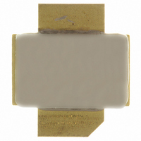
... BeO free package ■ In compliance with the 2002/95/EC european directive Description The SD57060- common source N-channel enhancement-mode lateral Field-Effect RF power transistor designed for broadband commercial and industrial applications at frequencies up to 1.0GHz. The SD57060-01 is designed for high gain and broadband performance operating in common source mode at 28V ...
Page 2
... Thermal data . . . . . . . . . . . . . . . . . . . . . . . . . . . . . . . . . . . . . . . . . . . . . . . 3 2 Electrical characteristics . . . . . . . . . . . . . . . . . . . . . . . . . . . . . . . . . . . . . 4 2.1 Static . . . . . . . . . . . . . . . . . . . . . . . . . . . . . . . . . . . . . . . . . . . . . . . . . . . . . 4 2.2 Dynamic . . . . . . . . . . . . . . . . . . . . . . . . . . . . . . . . . . . . . . . . . . . . . . . . . . . 4 3 Impedance . . . . . . . . . . . . . . . . . . . . . . . . . . . . . . . . . . . . . . . . . . . . . . . . . 5 4 Typical performance . . . . . . . . . . . . . . . . . . . . . . . . . . . . . . . . . . . . . . . . . 6 5 Common source s-parameter . . . . . . . . . . . . . . . . . . . . . . . . . . . . . . . . . 9 5.1 SD57060-01 (VDS = 13.5V IDS = 2A 5.2 SD57060 (VDS = 28V IDS = 2A Test circuit . . . . . . . . . . . . . . . . . . . . . . . . . . . . . . . . . . . . . . . . . . . . . . . . 11 7 Text circuit layout . . . . . . . . . . . . . . . . . . . . . . . . . . . . . . . . . . . . . . . . . . 13 8 Package mechanical data . . . . . . . . . . . . . . . . . . . . . . . . . . . . . . . . . . . . 14 9 Revision history . . . . . . . . . . . . . . . . . . . . . . . . . . . . . . . . . . . . . . . . . . . 16 2/16 SD57060-01 ...
Page 3
... SD57060-01 1 Electrical data 1.1 Maximum ratings Table 1. Absolute maximum ratings (T Symbol V (BR)DSS DISS STG 1.2 Thermal data Table 2. Thermal data Symbol R thJC (1) R thCS 1. Determined using a flat aluminum or copper heatsink with thermal compound applied (Dow Corning 340 or equivalent). CASE Parameter Drain-source voltage ...
Page 4
... C Test conditions 100 MHz MHz MHz DS Test conditions I = 100 945MHz 100 945MHz DQ OUT I = 100 945MHz DQ OUT I = 100 945MHz DQ OUT SD57060-01 Min Typ Max Unit 65 V µA 1 µA 1 2.0 5.0 V 0.7 0.8 V 2.5 mho 2.8 pF Min Typ Max Unit VSW 5:1 R ...
Page 5
... SD57060-01 3 Impedance Figure 2. Current conventions Table 4. Impedance data Freq. (MHz) 925 MHz 945 MHz 960 MHz Z (Ω 0.095 0 0.05 0 0.1 Impedance Z (Ω 0.48 1 0.25 1 0.130 5/16 ...
Page 6
... Pin (W) Figure 5. Efficiency vs output power 945 MHz Pout (W) 6/16 Figure Pout Figure 100 SD57060-01 Output power and power gain vs input power Pout Gain Vdd= 32V f= 945MHz Idq= 100mA 0.5 1 1.5 2 2.5 Pin (W) Efficiency vs output power f = 945 MHz 100 Output Power ( ...
Page 7
... SD57060-01 Figure 7. Output power vs drain-source voltage Drain-Source Voltage (V) Figure 9. Power gain vs output power Idq=400 mA Freq. 945 MHz Vdd= Pout (W) Figure 8. -15 Pin = 3 W Pin = 2 W -20 -25 -30 Pin = 1 W -35 -40 IDQ = 100 mA - 1945 MHz - -55 1 Figure 10. Safe operating area 10 Idq=100 Typical performance ...
Page 8
... Typical performance Figure 11. Capacitance vs drain-source voltage 1000 f = 1MHz Ciss 100 Coss 10 Crss Drain-Source Voltage (V) 8/ SD57060-01 ...
Page 9
... SD57060-01 5 Common source s-parameter 5.1 SD57060-01 (V Table 5. S-parameter FREQ s11 MAG s11 ang s21 MAG s21 ang s12 MAG s12 ang s22 MAG s22 ang (MHz) 50 0.896 60 0.896 70 0.869 80 0.869 90 0.897 100 0.897 150 0.9 200 0.905 250 0.912 300 0.92 350 0 ...
Page 10
... SD57060-01 0.0114 -3.8342 0.67 0.0113 -4.4852 0.672 0.0112 -5.1512 0.674 0.0111 -5.8379 0.677 0.011 -6.5533 0.679 0.011 -7.4226 0.683 0.0103 -12.13 ...
Page 11
... SD57060-01 6 Test circuit Figure 12. Test circuit schematic 1 Dimensions at component symbols are reference for component placement. 2 Gap between ground & transmission line = 0.056 [1.42] +0.002 [0.05] -0.000 [0.00] typ. 3 Dimensions of input and output component from edge of transmission lines. Test circuit Ref.7149484A 11/16 ...
Page 12
... ATC 100B SURFACE MOUNT CERAMIC CHIP CAPACITOR 0.1 µF / 500 V SURFACE MOUNT CERAMIC CHIP CAPACITOR 10 µ ALUMINIUM ELECTROLITIC RADIAL LEAD CAPACITOR 220 µ ALUMINIUM ELECTROLITIC RADIAL LEAD CAPACITOR ULTRALAM 2000, WOVEN FIBERGLASS REINFORCED PTFE. 0.030” THK, εr= 2.55 BOTH SIDES SD57060-01 ...
Page 13
... SD57060-01 7 Text circuit layout Figure 13. Test fixture Figure 14. Test circuit photomaster 6.4 inches Text circuit layout Ref. 7149484A Ref.7149484A 13/16 ...
Page 14
... Typ Max 5.21 5.71 2.16 2.92 5.59 6.09 8.89 9.40 9.40 9.91 0.11 0.15 0.89 1.14 1.45 1.70 2.67 3.94 SD57060-01 Inch Min Typ Max 0.205 0.225 0.085 0.115 0.220 0.240 0.350 0.370 0.370 0.390 0.004 0.006 0.035 0.045 0.057 0.067 ...
Page 15
... SD57060-01 9 Revision history Table 9. Document revision history Date 24-Mar-2003 11-Jul-2007 24-Aug-2007 Revision 5 First Issue. 6 Document reformatted, added lead free info 7 Cover page title updated Revision history Changes 15/16 ...
Page 16
... Australia - Belgium - Brazil - Canada - China - Czech Republic - Finland - France - Germany - Hong Kong - India - Israel - Italy - Japan - Malaysia - Malta - Morocco - Singapore - Spain - Sweden - Switzerland - United Kingdom - United States of America 16/16 Please Read Carefully: © 2007 STMicroelectronics - All rights reserved STMicroelectronics group of companies www.st.com SD57060-01 ...