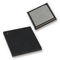
PIC18F65K90T-I/MR Microchip Technology, PIC18F65K90T-I/MR Datasheet - Page 395

PIC18F65K90T-I/MR
Manufacturer Part Number
PIC18F65K90T-I/MR
Description
32kB Flash, 2kB RAM, 1kB EE, NanoWatt XLP, LCD 64 QFN 9x9x0.9mm T/R
Manufacturer
Microchip Technology
Series
PIC® XLP™ 18Fr
Datasheet
1.PIC18F66K90-IMR.pdf
(570 pages)
Specifications of PIC18F65K90T-I/MR
Processor Series
PIC18F
Core
PIC
Data Bus Width
8 bit
Program Memory Type
Flash
Program Memory Size
32 KB
Data Ram Size
2 KB
Interface Type
I2C, SPI
Maximum Clock Frequency
64 MHz
Number Of Timers
8
Operating Supply Voltage
1.8 V to 5.5 V
Maximum Operating Temperature
+ 125 C
3rd Party Development Tools
52715-96, 52716-328, 52717-734, 52712-325, EWPIC18
Minimum Operating Temperature
- 40 C
On-chip Adc
12 bit, 16 Channel
Core Processor
PIC
Core Size
8-Bit
Speed
64MHz
Connectivity
I²C, LIN, SPI, UART/USART
Peripherals
Brown-out Detect/Reset, LCD, POR, PWM, WDT
Number Of I /o
53
Eeprom Size
1K x 8
Ram Size
2K x 8
Voltage - Supply (vcc/vdd)
1.8 V ~ 5.5 V
Data Converters
A/D 16x12b
Oscillator Type
Internal
Operating Temperature
-40°C ~ 85°C
Package / Case
64-VFQFN Exposed Pad
Lead Free Status / Rohs Status
Details
- Current page: 395 of 570
- Download datasheet (5Mb)
24.6
The comparator interrupt flag is set whenever any of
the following occurs:
• Low-to-high transition of the comparator output
• High-to-low transition of the comparator output
• Any change in the comparator output
The comparator interrupt selection is done by the
EVPOL<1:0>
(CMxCON<4:3>).
In order to provide maximum flexibility, the output of the
comparator may be inverted using the CPOL bit in the
CMxCON register (CMxCON<5>). This is functionally
identical to reversing the inverting and non-inverting
inputs of the comparator for a particular mode.
An interrupt is generated on the low-to-high or high-to-
low transition of the comparator output. This mode of
interrupt generation is dependent on EVPOL<1:0> in
the CMxCON register. When EVPOL<1:0> = 01 or 10 ,
the interrupt is generated on a low-to-high or high-to-
low transition of the comparator output. Once the
interrupt is generated, it is required to clear the interrupt
flag by software.
TABLE 24-2:
2009-2011 Microchip Technology Inc.
CPOL
Comparator Interrupts
0
1
bits
COMPARATOR INTERRUPT GENERATION
in
EVPOL<1:0>
the
00
01
10
11
00
01
10
11
CMxCON
register
Input Change
Comparator
V
V
V
V
V
V
V
V
V
V
V
V
V
V
V
V
IN
IN
IN
IN
IN
IN
IN
IN
IN
IN
IN
IN
IN
IN
IN
IN
+ > V
+ < V
+ > V
+ < V
+ > V
+ < V
+ > V
+ < V
+ > V
+ < V
+ > V
+ < V
+ > V
+ < V
+ > V
+ < V
IN
IN
IN
IN
IN
IN
IN
IN
IN
IN
IN
IN
IN
IN
IN
IN
-
-
-
-
-
-
-
-
-
-
-
-
-
-
-
-
PIC18F87K90 FAMILY
When EVPOL<1:0> = 11 , the comparator interrupt flag
is set whenever there is a change in the output value of
either comparator. Software will need to maintain infor-
mation about the status of the output bits, as read from
CMSTAT<7:5>, to determine the actual change that
occurred.
The CMPxIF bits (PIR6<2:0>) are the Comparator
Interrupt Flags. The CMPxIF bits must be reset by
clearing them. Since it is also possible to write a ‘ 1 ’ to
this register, a simulated interrupt may be initiated.
Table 24-2
to comparator input voltages and EVPOL bit settings.
Both the CMPxIE bits (PIE6<2:0>) and the PEIE bit
(INTCON<6>) must be set to enable the interrupt. In
addition, the GIE bit (INTCON<7>) must also be set. If
any of these bits are clear, the interrupt is not enabled,
though the CMPxIF bits will still be set if an interrupt
condition occurs.
A simplified diagram of the interrupt section is shown in
Figure
Note: CMPxIF will not be set when EVPOL<1:0> = 00 .
24-3.
CxOUT Transition
Low-to-High
High-to-Low
Low-to-High
High-to-Low
Low-to-High
High-to-Low
Low-to-High
High-to-Low
High-to-Low
Low-to-High
High-to-Low
Low-to-High
High-to-Low
Low-to-High
High-to-Low
Low-to-High
shows the interrupt generation with respect
DS39957D-page 395
Generated
Interrupt
Yes
Yes
Yes
Yes
Yes
Yes
Yes
Yes
No
No
No
No
No
No
No
No
Related parts for PIC18F65K90T-I/MR
Image
Part Number
Description
Manufacturer
Datasheet
Request
R

Part Number:
Description:
Manufacturer:
Microchip Technology Inc.
Datasheet:

Part Number:
Description:
Manufacturer:
Microchip Technology Inc.
Datasheet:

Part Number:
Description:
Manufacturer:
Microchip Technology Inc.
Datasheet:

Part Number:
Description:
Manufacturer:
Microchip Technology Inc.
Datasheet:

Part Number:
Description:
Manufacturer:
Microchip Technology Inc.
Datasheet:

Part Number:
Description:
Manufacturer:
Microchip Technology Inc.
Datasheet:

Part Number:
Description:
Manufacturer:
Microchip Technology Inc.
Datasheet:

Part Number:
Description:
Manufacturer:
Microchip Technology Inc.
Datasheet:


