PIC18F65K90T-I/PT Microchip Technology, PIC18F65K90T-I/PT Datasheet - Page 300
PIC18F65K90T-I/PT
Manufacturer Part Number
PIC18F65K90T-I/PT
Description
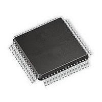
32kB Flash, 2kB RAM, 1kB EE, NanoWatt XLP, LCD 64 TQFP 10x10x1mm T/R
Manufacturer
Microchip Technology
Series
PIC® XLP™ 18Fr
Datasheet
1.PIC18F66K90-IMR.pdf
(570 pages)
Specifications of PIC18F65K90T-I/PT
Processor Series
PIC18F
Core
PIC
Data Bus Width
8 bit
Program Memory Type
Flash
Program Memory Size
32 KB
Data Ram Size
2 KB
Interface Type
I2C, SPI
Maximum Clock Frequency
64 MHz
Number Of Timers
8
Operating Supply Voltage
1.8 V to 5.5 V
Maximum Operating Temperature
+ 125 C
3rd Party Development Tools
52715-96, 52716-328, 52717-734, 52712-325, EWPIC18
Minimum Operating Temperature
- 40 C
On-chip Adc
12 bit, 16 Channel
Core Processor
PIC
Core Size
8-Bit
Speed
64MHz
Connectivity
I²C, LIN, SPI, UART/USART
Peripherals
Brown-out Detect/Reset, LCD, POR, PWM, WDT
Number Of I /o
53
Eeprom Size
1K x 8
Ram Size
2K x 8
Voltage - Supply (vcc/vdd)
1.8 V ~ 5.5 V
Data Converters
A/D 16x12b
Oscillator Type
Internal
Operating Temperature
-40°C ~ 85°C
Package / Case
64-TQFP
Lead Free Status / Rohs Status
Details
Available stocks
Company
Part Number
Manufacturer
Quantity
Price
Company:

Part Number:
PIC18F65K90T-I/PT
Manufacturer:
Microchip Technology
Quantity:
10 000
Company:
Part Number:
PIC18F65K90T-I/PTRSL
Manufacturer:
Microchip Technology
Quantity:
10 000


PIC18F87K90 FAMILY
20.11 Configuring the LCD Module
To configure the LCD module.
1.
2.
3.
DS39957D-page 300
Select the frame clock prescale, using bits,
LP<3:0> (LCDPS<3:0>).
Configure the appropriate pins to function as
segment drivers using the LCDSEx registers.
If using the internal reference resistors for
biasing, enable the internal reference ladder
and:
• Define the Mode A and Mode B interval by
• Define the low, medium or high ladder for
• Set the VLCDxPE bits and enable the
using the LRLAT<2:0> bits (LCDRL<2:0>)
Mode A and Mode B by using the LRLAP<1:0>
bits (LCDRL<7:6>) and the LRLBP<1:0> bits
(LCDRL<5:4>), respectively
LCDIRE bit (LCDREF<7>)
4.
5.
6.
7.
Configure the following LCD module functions
using the LCDCON register:
• Multiplex and Bias mode – LMUX<1:0> bits
• Timing Source – CS<1:0> bits
• Sleep mode – SLPEN bit
Write initial values to the pixel data registers,
LCDDATA0 through LCDDATA23.
Clear the LCD Interrupt Flag, LCDIF (PIR3<6>),
and if desired, enable the interrupt by setting bit,
LCDIE (PIE3<6>).
Enable the LCD module by setting bit, LCDEN
(LCDCON<7>).
2009-2011 Microchip Technology Inc.
Related parts for PIC18F65K90T-I/PT
Image
Part Number
Description
Manufacturer
Datasheet
Request
R

Part Number:
Description:
Manufacturer:
Microchip Technology Inc.
Datasheet:
Part Number:
Description:
Manufacturer:
Microchip Technology Inc.
Datasheet:
Part Number:
Description:
Manufacturer:
Microchip Technology Inc.
Datasheet:
Part Number:
Description:
Manufacturer:
Microchip Technology Inc.
Datasheet:
Part Number:
Description:
Manufacturer:
Microchip Technology Inc.
Datasheet:
Part Number:
Description:
Manufacturer:
Microchip Technology Inc.
Datasheet:
Part Number:
Description:
Manufacturer:
Microchip Technology Inc.
Datasheet:
Part Number:
Description:
Manufacturer:
Microchip Technology Inc.
Datasheet: