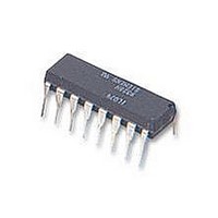
PCF8591P NXP Semiconductors, PCF8591P Datasheet - Page 12

PCF8591P
Manufacturer Part Number
PCF8591P
Description
IC, A/D AND D/A CONVERTER, 8BIT, 16-DIP
Manufacturer
NXP Semiconductors
Type
General Purposer
Specifications of PCF8591P
Number Of Channels
1
Number Of Adc's
1
Number Of Dac's
1
Adc/dac Resolution
8b
Interface Type
Serial (I2C)
Operating Supply Voltage (typ)
3.3/5V
Sample Rate
11.1KSPS
Number Of Adc Inputs
4
Number Of Dac Outputs
1
Operating Supply Voltage (max)
6V
Operating Supply Voltage (min)
2.5V
Operating Temperature (max)
85C
Operating Temperature (min)
-40C
Pin Count
16
Mounting
Through Hole
Supply Voltage Range
2.5V To 6V
Operating Temperature Range
-40°C To +85°C
Digital Ic Case Style
DIP
No. Of Pins
16
Linearity Error -
1.5LSB
Termination Type
DIP
Supply Voltage Max
8V
Input Channels Per Adc
1
Rohs Compliant
Yes
Filter Terminals
DIP
Conversion Time
90µs
Data Interface
I2C, Serial
Lead Free Status / RoHS Status
Compliant
Available stocks
Company
Part Number
Manufacturer
Quantity
Price
Company:
Part Number:
PCF8591P
Manufacturer:
SANYO
Quantity:
20 200
Company:
Part Number:
PCF8591P
Manufacturer:
NXP
Quantity:
5 510
Philips Semiconductors
8
The I
line (SDA) and a serial clock line (SCL). Both lines must be connected to a positive supply via a pull-up resistor. Data
transfer may be initiated only when the bus is not busy.
8.1
One data bit is transferred during each clock pulse. The data on the SDA line must remain stable during the HIGH period
of the clock pulse as changes in the data line at this time will be interpreted as a control signal.
8.2
Both data and clock lines remain HIGH when the bus is not busy. A HIGH-to-LOW transition of the data line, while the
clock is HIGH, is defined as the start condition (S). A LOW-to-HIGH transition of the data line while the clock is HIGH, is
defined as the stop condition (P).
2003 Jan 27
handbook, full pagewidth
handbook, full pagewidth
8-bit A/D and D/A converter
CHARACTERISTICS OF THE I
2
C-bus is for bidirectional, two-line communication between different ICs or modules. The two lines are a serial data
Bit transfer
Start and stop conditions
SDA
SCL
START condition
SDA
SCL
S
Fig.13 Definition of START and STOP condition.
2
C-BUS
data valid
data line
stable;
Fig.12 Bit transfer.
12
allowed
change
of data
STOP condition
MBC621
P
MBC622
SDA
SCL
Product specification
PCF8591


