CS82C54Z Intersil, CS82C54Z Datasheet - Page 12
CS82C54Z
Manufacturer Part Number
CS82C54Z
Description
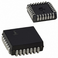
IC TIMER PROG CMOS 8MHZ 28-PLCC
Manufacturer
Intersil
Type
Programmable Timerr
Datasheet
1.CS82C54Z96.pdf
(22 pages)
Specifications of CS82C54Z
Frequency
8MHz
Voltage - Supply
4.5 V ~ 5.5 V
Current - Supply
10mA
Operating Temperature
0°C ~ 70°C
Package / Case
28-PLCC
Lead Free Status / RoHS Status
Lead free / RoHS Compliant
Count
-
Available stocks
Company
Part Number
Manufacturer
Quantity
Price
Company:

Part Number:
CS82C54Z
Manufacturer:
Intersil
Quantity:
1 808
Company:
Part Number:
CS82C54Z
Manufacturer:
Intersil
Quantity:
389
Part Number:
CS82C54Z
Manufacturer:
INTERSIL
Quantity:
20 000
Company:
Part Number:
CS82C54Z96
Manufacturer:
Intersil
Quantity:
1 500
Company:
Part Number:
CS82C54Z96
Manufacturer:
Intersil
Quantity:
2 853


If an initial count is written while GATE = 0, it will still be
loaded on the next CLK pulse. When GATE goes high, OUT
will go high N CLK pulses later; no CLK pulse is needed to
load the counter as this has already been done.
NOTES: The following conventions apply to all mode timing diagrams.
GATE
GATE
GATE
1. Counters are programmed for binary (not BCD) counting and for
2. The counter is always selected (CS always low).
3. CW stands for “Control Word”; CW = 10 means a control word of
4. LSB stands for Least significant “byte” of count.
5. Numbers below diagrams are count values. The lower number is
6. N stands for an undefined count.
7. Vertical lines show transitions between count values.
OUT
OUT
CLK
CLK
OUT
CLK
WR
WR
WR
reading/writing least significant byte (LSB) only.
10, Hex is written to the counter.
the least significant byte. The upper number is the most
significant byte. Since the counter is programmed to read/write
LSB only, the most significant byte cannot be read.
CW = 10
CW = 10
CW = 10
N
N
N
N
N
N
LSB = 4
LSB = 3
LSB = 3
N
N
N
FIGURE 9. MODE 0
N
N
N
0
3
0
4
0
3
12
LSB = 2
0
2
0
3
0
2
0
2
0
1
0
2
0
1
0
2
0
2
0
0
0
1
0
1
FF
FF
0
0
0
0
FF
FF
FF
FE
FF
FF
82C54
MODE 1: HARDWARE RETRIGGERABLE ONE-SHOT
OUT will be initially high. OUT will go low on the CLK pulse
following a trigger to begin the one-shot pulse, and will remain
low until the Counter reaches zero. OUT will then go high and
remain high until the CLK pulse after the next trigger.
After writing the Control Word and initial count, the Counter is
armed. A trigger results in loading the Counter and setting
OUT low on the next CLK pulse, thus starting the one-shot
pulse N CLK cycles in duration. The one-shot is retriggerable,
hence OUT will remain low for N CLK pulses after any trigger.
The one-shot pulse can be repeated without rewriting the
same count into the counter. GATE has no effect on OUT.
If a new count is written to the Counter during a one-shot
pulse, the current one-shot is not affected unless the
Counter is retriggerable. In that case, the Counter is loaded
with the new count and the one-shot pulse continues until
the new count expires.
GATE
GATE
GATE
OUT
OUT
OUT
CLK
CLK
CLK
WR
WR
WR
CW = 12
CW = 12
CW = 12
N
N
N
N
N
N
LSB = 3
LSB = 2
LSB = 3
N
N
N
FIGURE 10. MODE 1
N
N
N
N
N
N
LSB = 4
0
2
0
3
0
3
0
1
0
2
0
2
0
0
0
1
0
1
FF
FF
0
0
0
3
FF
FE
FF
FF
0
2
0
4
0
3
0
1
0
3
0
2
0
0
Related parts for CS82C54Z
Image
Part Number
Description
Manufacturer
Datasheet
Request
R

Part Number:
Description:
Intersil Corporation [CMOS Serial Controller Interface]
Manufacturer:
Intersil Corporation
Datasheet:
Part Number:
Description:
Manufacturer:
Intersil Corporation
Datasheet:
Part Number:
Description:
357-036-542-201 CARDEDGE 36POS DL .156 BLK LOPRO
Manufacturer:
Intersil Corporation
Datasheet:
Part Number:
Description:
1024-Word x 4-Bit LSI Static RAM
Manufacturer:
Intersil Corporation
Datasheet:
Part Number:
Description:
General Purpose NPN Transistor Arrays FN341.4
Manufacturer:
Intersil Corporation
Datasheet:
Part Number:
Description:
CMOS 16-Bit Microprocessor
Manufacturer:
Intersil Corporation
Datasheet:
Part Number:
Description:
Manufacturer:
Intersil Corporation
Datasheet:
Part Number:
Description:
Manufacturer:
Intersil Corporation
Datasheet:
Part Number:
Description:
Manufacturer:
Intersil Corporation
Datasheet:
Part Number:
Description:
Manufacturer:
Intersil Corporation
Datasheet:
Part Number:
Description:
CMOS 6-Bit Latch and Decoder Memory Interfaces
Manufacturer:
Intersil Corporation
Datasheet:
Part Number:
Description:
CA3046General Purpose NPN Transistor Arrays
Manufacturer:
Intersil Corporation
Datasheet:
Part Number:
Description:
Manufacturer:
Intersil Corporation
Datasheet:
Part Number:
Description:
TR909 DLC/FLC SLIC with Low Power Standby
Manufacturer:
Intersil Corporation
Datasheet:
Part Number:
Description:
Manufacturer:
Intersil Corporation
Datasheet: