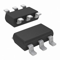
LTC6992HS6-1#TRMPBF Linear Technology, LTC6992HS6-1#TRMPBF Datasheet - Page 21

LTC6992HS6-1#TRMPBF
Manufacturer Part Number
LTC6992HS6-1#TRMPBF
Description
IC TIMERBLOX VOLT PWM TSOT23-6
Manufacturer
Linear Technology
Datasheet
1.LTC6992CDCB-1TRMPBF.pdf
(32 pages)
Specifications of LTC6992HS6-1#TRMPBF
Frequency
*
Voltage - Supply
*
Current - Supply
365µA
Operating Temperature
*
Package / Case
TSOT-23-6, TSOT-6
Count
*
Lead Free Status / RoHS Status
Lead free / RoHS Compliant
Other names
LTC6992HS6-1#TRMPBFTR
Available stocks
Company
Part Number
Manufacturer
Quantity
Price
APPLICATIONS INFORMATION
I
When operating with I
1.25μA to 20μA range, the master oscillator operates
outside of the 62.5kHz to 1MHz range in which it is most
accurate.
The oscillator will still function with reduced accuracy for
I
will be frozen in its current state. The output could halt in
a high or low state. This avoids introducing short pulses
while frequency modulating a very low frequency output.
At the other extreme, it is not recommended to operate
the master oscillator beyond 2MHz because the accuracy
of the DIV pin ADC will suffer.
SET
SET
< 1.25μA. At approximately 500nA, the oscillator output
Extremes (Master Oscillator Frequency Extremes)
DUTY CYCLE
Figure 11a. PWM Settling Time, 25% Duty Cycle
0.1V/DIV
5% DIV
2V/DIV
V
MOD
OUT
V
DIVCODE = 0
R
V
+
MOD
SET
= 3.3V
= 200k
= 0.3V ±40mV
SET
10μs/DIV
outside of the recommended
6992 F11a
–10
–15
–20
10
–5
Figure 10. PWM Frequency Response
5
0
0.001
0.01
f
MOD
÷1, 50%
/f
÷1, 80%
OUT
÷4, 15%
Pulse Width Modulation Bandwidth and Settling Time
The LTC6992 has a wide PWM bandwith, making it suitable
for a variety of feedback applications. Figure 10 shows that
the frequency response is flat for modulation frequencies
up to nearly 1/10 of the output frequency. Beyond that
point, some peaking may occur (depending on N
average duty cycle setting).
Duty cycle settling time depends on the master oscillator
frequency. Following a ±80mV step change in V
duty cycle takes approximately eight master clock cycles
(8 • t
Examples are shown in Figures 11a and 11b.
(Hz/Hz)
÷4, 50%
0.1
DUTY CYCLE
MASTER
Figure 11b. PWM Settling Time, 50% Duty Cycle
0.1V/DIV
5% DIV
2V/DIV
V
MOD
OUT
LTC6992-1/LTC6992-2/
÷16
6992 F10
LTC6992-3/LTC6992-4
) to settle to within 1% of the final value.
V
DIVCODE = 0
R
V
1
+
SET
MOD
= 3.3V
= 200k
= 0.5V ±40mV
10μs/DIV
6992 F11b
MOD
21
DIV
69921234f
, the
and


