ISL12028IVZ Intersil, ISL12028IVZ Datasheet
ISL12028IVZ
Specifications of ISL12028IVZ
Available stocks


Related parts for ISL12028IVZ

ISL12028IVZ Summary of contents
Page 1
... GND 7 8 SDA internal connection 1 1-888-INTERSIL or 1-888-468-3774 BlockLock™ trademark of Intersil Corporation or one of its subsidiaries. Copyright Intersil Americas Inc. 2005, 2006, 2008, 2010. November 30, 2010 2 C Bus™ Features • Real Time Clock/Calendar - Tracks time in Hours, Minutes and Seconds - Day of the Week, Day, Month and Year - 3 Selectable Frequency Outputs • ...
Page 2
... ISL12028IBZ 12028IBZ ISL12028IBAZ 12028IBAZ ISL12028IV27Z 12028 IV27Z ISL12028IV27AZ 12028 27AZ ISL12028IV30AZ 12028 30AZ ISL12028IVZ 12028 IVZ ISL12028IVAZ 12028 IVAZ ISL12028AIB27Z 12028AIB 27Z ISL12028AIV27Z 2028A IV27Z NOTES: 1. Add “-T*” suffix for tape and reel. Please refer to TB347 for details on reel specifications. ...
Page 3
Pin Descriptions PIN NUMBER SYMBOL 1 X1 The X1 pin is the input of an inverting amplifier and is intended to be connected to one pin of an external 32.768kHz quartz crystal The X2 pin is the output ...
Page 4
... Ld SOIC Package (Notes TSSOP Package (Note Maximum Junction Temperature (Plastic Package +150°C Storage Temperature . . . . . . . . . . . . . . . . . . . . . . . .-65°C to +150°C Pb-Free Reflow Profile .see link below http://www.intersil.com/pbfree/Pb-FreeReflow.asp Unless otherwise noted +2.7V to +5.5V and V = 3.3V. Boldface limits apply over the operating temperature range, -40°C to +85°C. ...
Page 5
Electrical Specifications Boldface limits apply over the operating temperature range, -40°C to +85°C. (Continued) SYMBOL PARAMETER RESET OUTPUT I Output Leakage Current LO V Output Low Voltage OL Watchdog Timer/Low Voltage Reset Parameters SYMBOL PARAMETER t V Detect to RESET ...
Page 6
Serial Interface (I C) Specifications SYMBOL PARAMETER t SCL Falling Edge to SDA Output AA Data Valid t Time the bus must be free before BUF the start of a new transmission t Clock LOW Time LOW t Clock ...
Page 7
Timing Diagrams SCL t SU:STA t HD:STA SDA (INPUT TIMING) SDA (OUTPUT TIMING) SCL 8TH BIT OF LAST BYTE SDA t RSP SCL SDA RESET START Note: All inputs are ignored during the active reset period (t V RESET V ...
Page 8
Typical Performance Curves 4.0 BSW = 3.5 SCL, SDA PULL-UPS = 0V 3.0 2.5 2.0 1.5 SCL, SDA PULL-UPS = V 1.0 0.5 BSW = 0.0 1.8 2.3 2.8 3.3 3.8 V (V) BAT ...
Page 9
Description The ISL12028 device is a Real Time Clock with clock/calendar, two polled alarms with integrated 512x8-bit EEPROM, oscillator compensation, CPU Supervisor (Power-On-Reset, Low Voltage Sensing and Watchdog Timer) and battery backup switch. The oscillator uses an external, low-cost 32.768kHz ...
Page 10
... For example, a >20ppm frequency deviation translates into an accuracy of >1 minute per month. These parameters are available from the crystal manufacturer. Intersil’s RTC family provides on-chip crystal compensation networks to adjust load-capacitance to tune oscillator frequency from -34ppm to +80ppm when using a 12.5pF load crystal. For more detailed information, see “ ...
Page 11
The state of the CCR can be read by performing a random read at any address in the CCR at any time. This returns the contents of that register location. Additional registers are read by performing a sequential read. The ...
Page 12
REG ADDR. TYPE NAME 7 003F Status SR BAT 0037 RTC Y2K 0 (SRAM) 0036 DW 0 0035 YR Y23 0034 MO 0 0033 DT 0 0032 HR MIL 0031 MN 0 0030 SC 0 0014 Control PWR SBIB (EEPROM ...
Page 13
Control Registers (Non-Volatile) The Control Bits and Registers described in the following are non-volatile. BL Register BP2, BP1, BP0 - Block Protect Bits The Block Protect Bits, BP2, BP1 and BP0, determine which blocks of the array are write protected. ...
Page 14
The effective series load capacitance is the combination of C and C as shown in Equation ---------------------------------- - C = LOAD ⎛ ⎞ ---------- - ---------- - + ⎝ ⎠ ...
Page 15
... The power control circuit accepts a V Many types of batteries can be used with Intersil RTC products. For example, 3.0V or 3.6V Lithium batteries are appropriate, and battery sizes are available that can power an Intersil RTC device for years. Another option is to use a SuperCap for applications where V Name and a V ...
Page 16
See “Application Section” on page 22 for more information. There are two options for setting the change-over conditions from V to Battery back-up mode. The BSW bit in the PWR DD register controls this operation. ...
Page 17
V > BAT BATHYS The Legacy Mode power control conditions are illustrated in Figure 15 VOLTAGE V BAT OFF FIGURE 15. BATTERY SWITCHOVER IN LEGACY MODE Power On Reset Application of power to the ISL12028 ...
Page 18
Figure 17). ACKNOWLEDGE Acknowledge is a software convention used to indicate successful data transfer. The transmitting device, either master or slave, will release the bus after ...
Page 19
DEVICE IDENTIFIER Array CCR FIGURE 19. SLAVE ADDRESS, WORD ADDRESS, AND DATA BYTES (64 BYTE PAGES) Following the Slave Byte is a two byte word address. The word address is ...
Page 20
SIGNALS FROM THE MASTER SDA BUS SIGNALS FROM THE SLAVE S T SIGNALS FROM A THE MASTER R T ADDRESS SDA BUS 1 SIGNALS FROM THE SLAVE 6 BYTES ADDRESS = 5 ADDRESS POINTER ENDS AT ADDR = 5 FIGURE ...
Page 21
In this way, a current address read immediately after the power on reset can download the entire contents of memory starting at the first location. Upon receipt of the Slave Address Byte ...
Page 22
... In addition to the analog compensation afforded by the adjustable load capacitance, a digital compensation feature is available for the Intersil RTC family. There are three bits known as the Digital Trimming Register or DTR, and they operate by adding or skipping pulses in the clock signal. The range provided is ± ...
Page 23
... TABLE 10. CRYSTAL MANUFACTURERS PART NUMBER . XTAL1 XTAL1 32.768kHz 32.768kGz FIGURE 27. SUGGESTED LAYOUT FOR INTERSIL RTC IN SO-14 NOTES kHz Down to 20ppm if desired °C Typically the value used for most crystals °C pF Ω k For best oscillator performance +25°C FREQUENCY TEMP RANGE TOLERANCE (° ...
Page 24
... Applying a scope probe can possibly cause a faulty oscillator to start up, hiding other issues (although in the Intersil RTC’s, the internal circuitry assures startup when using the proper crystal and layout). ...
Page 25
... Backup Battery Operation Many types of batteries can be used with the Intersil RTC products. 3.0V or 3.6V Lithium batteries are appropriate, and sizes are available that can power a Intersil RTC device for years. Another option is to use a supercapacitor for applications where V may disappear intermittently for short DD periods of time ...
Page 26
V (3.0V) BAT V DD (2.63V) V RESET V TRIP (2.2V) RESET I BAT (V FIGURE 29. EXAMPLE RESET OPERATION IN MODE (3.0V) BAT V DD (2.63V) V RESET V TRIP (2.2V) RESET I BAT ...
Page 27
... Accordingly, the reader is cautioned to verify that data sheets are current before placing orders. Information furnished by Intersil is believed to be accurate and reliable. However, no responsibility is assumed by Intersil or its subsidiaries for its use; nor for any infringements of patents or other rights of third parties which may result from its use ...
Page 28
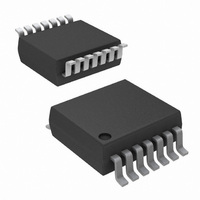
Package Outline Drawing M14.15 14 LEAD NARROW BODY SMALL OUTLINE PLASTIC PACKAGE Rev 1, 10/09 14 3 PIN NO.1 ID MARK 5 0.31-0.51 0. A-B D TOP VIEW 1.75 MAX 1.27 SIDE VIEW ...
Page 29
Package Outline Drawing M14.173 14 LEAD THIN SHRINK SMALL OUTLINE PACKAGE (TSSOP) Rev 3, 10/09 1 5.00 ±0.10 14 6.40 4.40 ±0. 0. 0.65 TOP VIEW H C SEATING PLANE 0.10 C SIDE VIEW ...