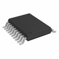
AD7822BRU Analog Devices Inc, AD7822BRU Datasheet - Page 12

AD7822BRU
Manufacturer Part Number
AD7822BRU
Description
IC ADC 8BIT 1CH 2MSPS 20TSSOP
Manufacturer
Analog Devices Inc
Datasheet
1.AD7822BRZ.pdf
(28 pages)
Specifications of AD7822BRU
Rohs Status
RoHS non-compliant
Number Of Bits
8
Sampling Rate (per Second)
2M
Data Interface
Parallel
Number Of Converters
1
Power Dissipation (max)
36mW
Voltage Supply Source
Single Supply
Operating Temperature
-40°C ~ 85°C
Mounting Type
Surface Mount
Package / Case
20-TSSOP (0.173", 4.40mm Width)
Available stocks
Company
Part Number
Manufacturer
Quantity
Price
Company:
Part Number:
AD7822BRUZ
Manufacturer:
Analog Devices Inc
Quantity:
135
Part Number:
AD7822BRUZ
Manufacturer:
ADI/亚德诺
Quantity:
20 000
AD7822/AD7825/AD7829
V
offset to the V
accommodate bipolar signals by applying V
circuit before V
driven by an external source, the source can be directly tied to
the level-shifting circuitry (see Figure 13). However, if the
internal V
output, it must be buffered before applying it to the level-
shifting circuitry because the V
approximately 6 kΩ (see Figure 14).
MID
3V
5V
4V
3V
2V
1V
2V
1V
can be used to remove offsets in a system by applying the
V
MID
V
IN
V
MID
V
V
MID
V
MID
DD
DD
Figure 11. Analog Input Span Variation with V
= N/C (1.25V)
, that is, the default value, is being used as an
= 3V
= 5V
= N/C (1V)
MID
IN
Figure 12. Removing Offsets Using V
, as shown in Figure 13. When V
pin as shown in Figure 12, or it can be used to
V
MID
V
MID
= 1.5V
V
MID
= 2.5V
MID
V
V
MID
IN
pin has an impedance of
V
MID
= 2V
V
MID
INPUT SIGNAL RANGE
INPUT SIGNAL RANGE
MID
FOR VARIOUS V
FOR VARIOUS V
AD7822/
AD7825/
AD7829
= 3.75V
to a level-shifting
MID
MID
MID
is being
MID
MID
Rev. C | Page 12 of 28
NOTE: Although there is a V
reference of 2.5 V can be sourced, or to which an external
reference can be applied, this does not provide an option of
varying the value of the voltage reference. As stated in the
specifications for the AD7822/AD7825/AD7829, the input
voltage range at this pin is 2.5 V ± 2%.
Analog Input Structure
Figure 15 shows an equivalent circuit of the analog input
structure of the AD7822/AD7825/AD7829. The two diodes,
D1 and D2, provide ESD protection for the analog inputs. Care
must be taken to ensure that the analog input signal never
exceeds the supply rails by more than 200 mV. Doing so causes
these diodes to become forward biased and start conducting
current into the substrate. A maximum current of 20 mA can be
conducted by these diodes without causing irreversible damage
to the part. However, it is worth noting that a small amount of
current (1 mA) being conducted into the substrate, due to an
overvoltage on an unselected channel, can cause inaccurate
conversions on a selected channel.
0V
0V
V
V
Figure 13. Accommodating Bipolar Signals Using External V
Figure 14. Accommodating Bipolar Signals Using Internal V
V
V
2.5V
R3
R2
R3
R2
R4
R4
R1
R1
EXTERNAL
REF
V
2.5V
V
V
MID
0V
0V
2.5V
IN
IN
pin from which a voltage
V
V
V
V
V
V
IN
IN
MID
REF
MID
REF
AD7822/
AD7825/
AD7829
AD7822/
AD7825/
AD7829
MID
MID


