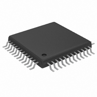
MAX1184ECM+TD Maxim Integrated Products, MAX1184ECM+TD Datasheet - Page 12

MAX1184ECM+TD
Manufacturer Part Number
MAX1184ECM+TD
Description
IC ADC 10BIT 20MSPS DL 48-TQFP
Manufacturer
Maxim Integrated Products
Datasheet
1.MAX1184ECMD.pdf
(21 pages)
Specifications of MAX1184ECM+TD
Number Of Bits
10
Sampling Rate (per Second)
20M
Data Interface
Parallel
Number Of Converters
2
Power Dissipation (max)
150mW
Voltage Supply Source
Single Supply
Operating Temperature
-40°C ~ 85°C
Mounting Type
Surface Mount
Package / Case
48-TQFP Exposed Pad, 48-eTQFP, 48-HTQFP, 48-VQFP
Lead Free Status / RoHS Status
Lead free / RoHS Compliant
Dual 10-Bit, 20Msps, 3V, Low-Power ADC with
Internal Reference and Parallel Outputs
Figure 2 displays a simplified functional diagram of the
input track-and-hold (T/H) circuits in both track-and-
hold mode. In track mode, switches S1, S2a, S2b, S4a,
S4b, S5a, and S5b are closed. The fully differential cir-
cuits sample the input signals onto the two capacitors
(C2a and C2b) through switches S4a and S4b. S2a and
12
Figure 2. MAX1184 T/H Amplifiers
INA+
INA-
INB+
INB-
______________________________________________________________________________________
S4a
S4b
S4a
S4b
S4c
S4c
Input Track-and-Hold (T/H) Circuits
C2a
C2b
C2a
C2b
S2a
S2a
INTERNAL
INTERNAL
INTERNAL
INTERNAL
S1
S1
BIAS
BIAS
BIAS
BIAS
S2b
S2b
C1a
C1b
C1a
C1b
COM
COM
COM
COM
HOLD
S5a
S5b
S5a
S5b
TRACK
S3a
S3b
S3a
S3b
HOLD
TRACK
OUT
OUT
OUT
OUT
MAX1184
CLK
INTERNAL
NONOVERLAPPING
CLOCK SIGNALS
S2b set the common mode for the amplifier input, and
open simultaneously with S1, sampling the input wave-
form. Switches S4a and S4b are then opened before
switches S3a and S3b, connect capacitors C1a and
C1b to the output of the amplifier, and switch S4c is
closed. The resulting differential voltages are held on
capacitors C2a and C2b. The amplifiers are used to
charge capacitors C1a and C1b to the same values
originally held on C2a and C2b. These values are then
presented to the first-stage quantizers and isolate the
pipelines from the fast-changing inputs. The wide input
bandwidth T/H amplifiers allow the MAX1184 to track-
and-sample/hold analog inputs of high frequencies (>
Nyquist). The ADC inputs (INA+, INB+, INA-, and INB-)
can be driven either differentially or single-ended.
Match the impedance of INA+ and INA-, as well as
INB+ and INB- and set the common-mode voltage to
midsupply (V
The full-scale range of the MAX1184 is determined by the
internally generated voltage difference between REFP
(V
full-scale range for both on-chip ADCs is adjustable
through the REFIN pin, which is provided for this purpose.
REFOUT, REFP, COM (V
buffered low-impedance outputs.
The MAX1184 provides three modes of reference operation:
In internal reference mode, connect the internal refer-
ence output REFOUT to REFIN through a resistor (e.g.,
10kΩ) or resistor-divider, if an application requires a
reduced full-scale range. For stability and noise filtering
purposes, bypass REFIN with a >10nF capacitor to
GND. In internal reference mode, REFOUT, COM,
REFP, and REFN become low-impedance outputs.
In buffered external reference mode, adjust the refer-
ence voltage levels externally by applying a stable and
accurate voltage at REFIN. In this mode, COM, REFP,
and REFN become outputs. REFOUT may be left open
or connected to REFIN through a >10kΩ resistor.
In unbuffered external reference mode, connect REFIN
to GND. This deactivates the on-chip reference buffers
for REFP, COM, and REFN. With their buffers shut
down, these nodes become high impedance and may
be driven through separate external reference sources.
DD
• Internal reference mode
• Buffered external reference mode
• Unbuffered external reference mode
/2 + V
REFIN
DD
/2) for optimum performance.
/4) and REFN (V
Analog Inputs and Reference
DD
/2), and REFN are internally
DD
/2 - V
Configurations
REFIN
/4). The


