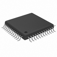
MAX1184ECM+TD Maxim Integrated Products, MAX1184ECM+TD Datasheet - Page 16

MAX1184ECM+TD
Manufacturer Part Number
MAX1184ECM+TD
Description
IC ADC 10BIT 20MSPS DL 48-TQFP
Manufacturer
Maxim Integrated Products
Datasheet
1.MAX1184ECMD.pdf
(21 pages)
Specifications of MAX1184ECM+TD
Number Of Bits
10
Sampling Rate (per Second)
20M
Data Interface
Parallel
Number Of Converters
2
Power Dissipation (max)
150mW
Voltage Supply Source
Single Supply
Operating Temperature
-40°C ~ 85°C
Mounting Type
Surface Mount
Package / Case
48-TQFP Exposed Pad, 48-eTQFP, 48-HTQFP, 48-VQFP
Lead Free Status / RoHS Status
Lead free / RoHS Compliant
Dual 10-Bit, 20Msps, 3V, Low-Power ADC with
Internal Reference and Parallel Outputs
A RF transformer (Figure 6) provides an excellent solu-
tion to convert a single-ended source signal to a fully
differential signal, required by the MAX1184 for opti-
mum performance. Connecting the center tap of the
transformer to COM provides a V
the input. Although a 1:1 transformer is shown, a step-
up transformer may be selected to reduce the drive
requirements. A reduced signal swing from the input
driver, such as an op amp, may also improve the over-
all distortion.
In general, the MAX1184 provides better SFDR and
THD with fully-differential input signals than single-
16
Figure 6. Transformer-Coupled Input Drive
V
V
IN
IN
______________________________________________________________________________________
0.1µF
0.1µF
N.C.
N.C.
MINICIRCUITS
MINICIRCUITS
3
1
1
3
2
2
TT1–6
TT1–6
T1
T1
5
4
5
4
6
6
Using Transformer Coupling
2.2µF
2.2µF
25Ω
25Ω
25Ω
25Ω
0.1µF
0.1µF
22pF
22pF
22pF
22pF
DD
/2 DC level shift to
INA+
INA-
INB+
INB-
COM
MAX1184
ended drive, especially for very high input frequencies.
In differential input mode, even-order harmonics are
lower as both inputs (INA+, INA- and/or INB+, INB-) are
balanced, and each of the ADC inputs only requires half
the signal swing compared to a single-ended mode.
Figure 7 shows an AC-coupled, single-ended applica-
tion. Amplifiers like the MAX4108 provide high speed,
high bandwidth, low noise, and low distortion to main-
tain the integrity of the input signal.
Figure 7: Using an Op Amp for Single-Ended, AC-Coupled
Input Drive
V
V
IN
IN
MAX4108
MAX4108
Single-Ended AC-Coupled Input Signal
100Ω
100Ω
100Ω
100Ω
0.1µF
0.1µF
REFP
REFN
REFP
REFN
1kΩ
1kΩ
1kΩ
1kΩ
0.1µF
0.1µF
R
50Ω
R
50Ω
ISO
ISO
22pF
22pF
22pF
22pF
R
50Ω
C
50Ω
C
C
C
R
ISO
IN
ISO
IN
IN
IN
INA+
COM
INA-
INB+
INB-
MAX1184


