X9400WP24 Intersil, X9400WP24 Datasheet - Page 19
X9400WP24
Manufacturer Part Number
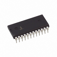
X9400WP24
Description
IC DCP QUAD 10K 64TP 24DIP
Manufacturer
Intersil
Series
XDCP™r
Datasheet
1.X9400WV24-2.7.pdf
(19 pages)
Specifications of X9400WP24
Taps
64
Resistance (ohms)
10K
Number Of Circuits
4
Temperature Coefficient
300 ppm/°C Typical
Memory Type
Non-Volatile
Interface
SPI, 3-Wire Serial
Voltage - Supply
4.5 V ~ 5.5 V
Operating Temperature
0°C ~ 70°C
Mounting Type
Through Hole
Resistance In Ohms
10K
Lead Free Status / RoHS Status
Contains lead / RoHS non-compliant
Package / Case
-


Thin Shrink Small Outline Package Family (TSSOP)
Intersil products are sold by description only. Intersil Corporation reserves the right to make changes in circuit design, software and/or specifications at any time without
notice. Accordingly, the reader is cautioned to verify that data sheets are current before placing orders. Information furnished by Intersil is believed to be accurate and
reliable. However, no responsibility is assumed by Intersil or its subsidiaries for its use; nor for any infringements of patents or other rights of third parties which may result
from its use. No license is granted by implication or otherwise under any patent or patent rights of Intersil or its subsidiaries.
C
SEATING
PLANE
N LEADS
E
0.10 C
A
0.25
E1
B
c
A2
M
e
All Intersil U.S. products are manufactured, assembled and tested utilizing ISO9000 quality systems.
N
1
C A B
A1
SEE DETAIL “X”
Intersil Corporation’s quality certifications can be viewed at www.intersil.com/design/quality
TOP VIEW
b
For information regarding Intersil Corporation and its products, see www.intersil.com
DETAIL X
SIDE VIEW
D
END VIEW
19
L1
(N/2)+1
L
(N/2)
0.10
M
0° - 8°
0.05
PIN #1 I.D.
C A B
2X
N/2 LEAD TIPS
A
GAUGE
PLANE
0.20 C
0.25
B A
H
X9400
MDP0044
THIN SHRINK SMALL OUTLINE PACKAGE FAMILY
NOTES:
SYMBOL 14 LD 16 LD 20 LD 24 LD 28 LD TOLERANCE
1. Dimension “D” does not include mold flash, protrusions or gate
2. Dimension “E1” does not include interlead flash or protrusions.
3. Dimensions “D” and “E1” are measured at dAtum Plane H.
4. Dimensioning and tolerancing per ASME Y14.5M-1994.
A1
A2
E1
L1
D
A
b
E
e
L
c
burrs. Mold flash, protrusions or gate burrs shall not exceed
0.15mm per side.
Interlead flash and protrusions shall not exceed 0.25mm per
side.
1.20
0.10
0.90
0.25
0.15
5.00
6.40
4.40
0.65
0.60
1.00
1.20
0.10
0.90
0.25
0.15
5.00
6.40
4.40
0.65
0.60
1.00
1.20
0.10
0.90
0.25
0.15
6.50
6.40
4.40
0.65
0.60
1.00
1.20
0.10
0.90
0.25
0.15
7.80
6.40
4.40
0.65
0.60
1.00
1.20
0.10
0.90
0.25
0.15
9.70
6.40
4.40
0.65
0.60
1.00
+0.05/-0.06
+0.05/-0.06
Rev. E 12/02
Reference
±0.05
±0.05
±0.10
±0.10
±0.15
Basic
Basic
July 28, 2006
Max
FN8189.3
Related parts for X9400WP24
Image
Part Number
Description
Manufacturer
Datasheet
Request
R

Part Number:
Description:
Intersil Corporation [CMOS Serial Controller Interface]
Manufacturer:
Intersil Corporation
Datasheet:
Part Number:
Description:
Manufacturer:
Intersil Corporation
Datasheet:
Part Number:
Description:
357-036-542-201 CARDEDGE 36POS DL .156 BLK LOPRO
Manufacturer:
Intersil Corporation
Datasheet:
Part Number:
Description:
1024-Word x 4-Bit LSI Static RAM
Manufacturer:
Intersil Corporation
Datasheet:
Part Number:
Description:
General Purpose NPN Transistor Arrays FN341.4
Manufacturer:
Intersil Corporation
Datasheet:
Part Number:
Description:
CMOS 16-Bit Microprocessor
Manufacturer:
Intersil Corporation
Datasheet:
Part Number:
Description:
Manufacturer:
Intersil Corporation
Datasheet:
Part Number:
Description:
Manufacturer:
Intersil Corporation
Datasheet:
Part Number:
Description:
Manufacturer:
Intersil Corporation
Datasheet:
Part Number:
Description:
Manufacturer:
Intersil Corporation
Datasheet:
Part Number:
Description:
CMOS 6-Bit Latch and Decoder Memory Interfaces
Manufacturer:
Intersil Corporation
Datasheet:
Part Number:
Description:
CA3046General Purpose NPN Transistor Arrays
Manufacturer:
Intersil Corporation
Datasheet:
Part Number:
Description:
Manufacturer:
Intersil Corporation
Datasheet:
Part Number:
Description:
TR909 DLC/FLC SLIC with Low Power Standby
Manufacturer:
Intersil Corporation
Datasheet:
Part Number:
Description:
Manufacturer:
Intersil Corporation
Datasheet: