CAT5271ZI-50-GT3 ON Semiconductor, CAT5271ZI-50-GT3 Datasheet - Page 11
CAT5271ZI-50-GT3
Manufacturer Part Number
CAT5271ZI-50-GT3
Description
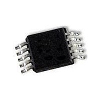
IC POT DPP 50K 256TAP 10MSOP
Manufacturer
ON Semiconductor
Datasheet
1.CAT5271ZI-50-GT3.pdf
(14 pages)
Specifications of CAT5271ZI-50-GT3
Package / Case
10-MSOP, Micro10™, 10-uMAX, 10-uSOP
Mounting Type
Surface Mount
Voltage - Supply
2.5 V ~ 5.5 V
Operating Temperature
-40°C ~ 85°C
Temperature Coefficient
100 ppm/°C Typical
Interface
I²C, 2-Wire Serial
Resistance In Ohms
50K
Number Of Circuits
2
Memory Type
Volatile
Taps
256
Number Of Pots
Dual
Taps Per Pot
256
Resistance
50 KOhms
Wiper Memory
Volatile
Digital Interface
I2C
Operating Supply Voltage
2.7 V to 5.5 V
Supply Current
0.3 uA
Maximum Operating Temperature
+ 85 C
Minimum Operating Temperature
- 40 C
Description/function
Dual 256-Tap Digital Potentiometer
Mounting Style
SMD/SMT
Supply Voltage (max)
5.5 V
Supply Voltage (min)
2.7 V
Tolerance
20 %
Lead Free Status / RoHS Status
Lead free / RoHS Compliant


INSTRUCTION AND REGISTER DESCRIPTION
SLAVE ADDRESS BYTE
is called the Slave Address Byte. The most significant seven
bits of the slave address are a device type identifier. For the
CAT5271, these bits are fixed at 0101111. For CAT5273, the
first five bits are fixed as 01011, and the next two bits of the
device identifier are determined by the logic levels on the
AD1 and AD0 pins. The following bit (R/W) selects
between a Read or a Write operation. If the bit is logic high,
then a Read instruction is performed. If the bit is low, then
the Write command is executed.
INSTRUCTION BYTE
bytes in length. The basic sequence of the two instructions
is illustrated in Table 10 and 11.
Write Operation
selects between the potentiometer 1 and 2: a logic low is for
the potentiometer 1, and a logic high is for potentiometer 2.
causes an open circuit at terminal A while shorting the wiper
terminal W to terminal B. The “shutdown” operation does
not change the contents of the wiper register. When the
shutdown bit, SD, goes back to a logic low, the previous
wiper position is restored. Also during shutdown, new
settings can be programmed. As soon as the device is
returned from shutdown, the wiper position is set according
to the wiper register value.
The first byte sent to the CAT5271 from the master/processor
Write and Read instructions are respectively three and two
In the write instruction, the second byte first bit (A0)
The following bit (SD) is the shutdown bit. A logic high
http://onsemi.com
11
care bits.
Read Operation
the acknowledgment of the slave address byte. Data is
transmitted over the serial bus in sequences.
Read command. The addressed channel is the one that is
previously selected in the write mode. If it desired to read the
potentiometer wiper register values of both channels, the
first potentiometer must be addressed in write mode and
then change to read mode to read the first channel value.
After that, the user must return the device to write mode with
the second potentiometer selected and read the second
potentiometer wiper register value in read mode. It is not
necessary for users to issue the third data byte in write mode
for subsequent read operation.
Wiper Control
Control Register (WCR). The Wiper Control Register
output is decoded to select one of 256 switches along its
resistor array. The contents of the WCR may be written by
the host via Write instruction.
loses its contents when the CAT5271/CAT5273 is
powered−down. Upon power−up, the wiper is set to
midscale and may be repositioned anytime after the power
has become stable.
The remainder of the bits in the instruction byte are don’t
In the read mode, the data byte follows immediately after
There is no potentiometer channel selection bit in the
The CAT5271/CAT5273 contains two 8−bit Wiper
The Wiper Control Registers are a volatile register that
Related parts for CAT5271ZI-50-GT3
Image
Part Number
Description
Manufacturer
Datasheet
Request
R

Part Number:
Description:
Dual 256-Position I2C Compatible Digital Potentiometer
Manufacturer:
ONSEMI [ON Semiconductor]
Datasheet:

Part Number:
Description:
Dual 256-position I C Compatible Digital Potentiometer
Manufacturer:
ON Semiconductor
Datasheet:
Part Number:
Description:
ON Semiconductor [VOLTAGE REGULATOR]
Manufacturer:
ON Semiconductor
Datasheet:
Part Number:
Description:
357-036-542-201 CARDEDGE 36POS DL .156 BLK LOPRO
Manufacturer:
ON Semiconductor
Datasheet:
Part Number:
Description:
357-036-542-201 CARDEDGE 36POS DL .156 BLK LOPRO
Manufacturer:
ON Semiconductor
Datasheet:
Part Number:
Description:
357-036-542-201 CARDEDGE 36POS DL .156 BLK LOPRO
Manufacturer:
ON Semiconductor
Datasheet:
Part Number:
Description:
357-036-542-201 CARDEDGE 36POS DL .156 BLK LOPRO
Manufacturer:
ON Semiconductor
Datasheet:
Part Number:
Description:
357-036-542-201 CARDEDGE 36POS DL .156 BLK LOPRO
Manufacturer:
ON Semiconductor
Datasheet:
Part Number:
Description:
357-036-542-201 CARDEDGE 36POS DL .156 BLK LOPRO
Manufacturer:
ON Semiconductor
Datasheet:
Part Number:
Description:
357-036-542-201 CARDEDGE 36POS DL .156 BLK LOPRO
Manufacturer:
ON Semiconductor
Datasheet:
Part Number:
Description:
357-036-542-201 CARDEDGE 36POS DL .156 BLK LOPRO
Manufacturer:
ON Semiconductor
Datasheet:
Part Number:
Description:
357-036-542-201 CARDEDGE 36POS DL .156 BLK LOPRO
Manufacturer:
ON Semiconductor
Datasheet:
Part Number:
Description:
357-036-542-201 CARDEDGE 36POS DL .156 BLK LOPRO
Manufacturer:
ON Semiconductor
Datasheet:
Part Number:
Description:
Manufacturer:
ON Semiconductor
Datasheet: