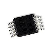
CAT5271ZI-50-GT3 ON Semiconductor, CAT5271ZI-50-GT3 Datasheet - Page 9

CAT5271ZI-50-GT3
Manufacturer Part Number
CAT5271ZI-50-GT3
Description
IC POT DPP 50K 256TAP 10MSOP
Manufacturer
ON Semiconductor
Datasheet
1.CAT5271ZI-50-GT3.pdf
(14 pages)
Specifications of CAT5271ZI-50-GT3
Package / Case
10-MSOP, Micro10™, 10-uMAX, 10-uSOP
Mounting Type
Surface Mount
Voltage - Supply
2.5 V ~ 5.5 V
Operating Temperature
-40°C ~ 85°C
Temperature Coefficient
100 ppm/°C Typical
Interface
I²C, 2-Wire Serial
Resistance In Ohms
50K
Number Of Circuits
2
Memory Type
Volatile
Taps
256
Number Of Pots
Dual
Taps Per Pot
256
Resistance
50 KOhms
Wiper Memory
Volatile
Digital Interface
I2C
Operating Supply Voltage
2.7 V to 5.5 V
Supply Current
0.3 uA
Maximum Operating Temperature
+ 85 C
Minimum Operating Temperature
- 40 C
Description/function
Dual 256-Tap Digital Potentiometer
Mounting Style
SMD/SMT
Supply Voltage (max)
5.5 V
Supply Voltage (min)
2.7 V
Tolerance
20 %
Lead Free Status / RoHS Status
Lead free / RoHS Compliant
I
processor or controller, and the device being controlled is the
slave. The master will always initiate data transfers and
provide the clock for both transmit and receive operations.
Therefore, CAT5271/CAT5273 will be considered a slave
device in all applications.
START Condition
device, and is defined as a high to low transition of SDA
when SCL is high. The CAT5271/CAT5273 monitors the
SDA and SCL lines and will not respond until this condition
is met.
STOP Condition
determines the STOP condition. All operations must end
with a STOP condition.
Device Addressing
START condition. The Master then sends the address of the
particular slave device it is requesting. The seven most
significant bits of the 8−bit slave address are fixed as
0101111 for the CAT5271. For CAT5273 the first five bits
are fixed as 01011, and the next two bits are
pin−programmable device address bits (AD1 and AD0). The
next bit (R/W) selects between the type of the instruction
2
C Bus Protocol
The following defines the features of the I
The device controlling the transfer is a master, typically a
The START condition precedes all commands to the
A low to high transition of SDA when SCL is high
The bus Master begins a transmission by sending a
SDA OUT
1. Data transfer may be initiated only when the bus is
2. During a data transfer, the data line must remain
SDA IN
not busy.
stable whenever the clock line is high. Any
changes in the data line while the clock is high
will be interpreted as a START or STOP condition.
SCL
t SU:STA
t F
t HD:STA
t LOW
2
C bus protocol:
t AA
Figure 18. Bus Timing Diagram
t HD:DAT
t HIGH
http://onsemi.com
t LOW
9
Read or Write. If the bit is logic high, then a Read instruction
is performed. If the bit is logic low, then the Write command
is executed.
address byte, the CAT5271/CAT5273 monitors the bus and
responds with an acknowledge (on the SDA line) when its
address matches the transmitted slave address.
Acknowledge
required to generate an acknowledge. The Acknowledging
device pulls down the SDA line during the ninth clock cycle,
signaling that it received the 8 bits of data.
after receiving a START condition and its slave address. If
the device has been selected along with a write operation, it
responds with an acknowledge after receiving each 8−bit
byte.
transmits 8 bits of data, releases the SDA line, and monitors
the line for an acknowledge. Once it receives this
acknowledge, the CAT5271/CAT5273 will continue to
transmit data. If no acknowledge is sent by the Master, the
device terminates data transmission and waits for a STOP
condition.
Write Operation
condition and the slave address information to the Slave
device. After the Slave generates an acknowledge, the
Master sends the instruction byte. After receiving another
acknowledge from the Slave, the Master device transmits
the data to be written into the wiper register. The CAT5271/
CAT5273 acknowledges once more and the Master
generates the STOP condition.
t DH
After the Master sends a START condition and the slave
After a successful data transfer, each receiving device is
The CAT5271/CAT5273 responds with an acknowledge
When the CAT5271/CAT5273 is in a READ mode it
In the Write mode, the Master device sends the START
t SU:DAT
t R
t SU:STO
t BUF


