X9241US Intersil, X9241US Datasheet - Page 8

X9241US
Manufacturer Part Number
X9241US
Description
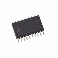
IC DCP QUAD 50K 64TP 20SOIC
Manufacturer
Intersil
Series
XDCP™r
Specifications of X9241US
Taps
64
Resistance (ohms)
50K
Number Of Circuits
4
Temperature Coefficient
30 ppm/°C Typical
Memory Type
Non-Volatile
Interface
I²C, 2-Wire Serial
Voltage - Supply
4.5 V ~ 5.5 V
Operating Temperature
0°C ~ 70°C
Mounting Type
Surface Mount
Package / Case
20-SOIC (7.5mm Width)
Resistance In Ohms
50K, 50K, 50K, 50K
Lead Free Status / RoHS Status
Contains lead / RoHS non-compliant
Available stocks
Company
Part Number
Manufacturer
Quantity
Price
Part Number:
X9241US
Manufacturer:
XICOR
Quantity:
20 000
Cascade Mode
The X9241 provides a mechanism for cascading the
arrays. That is, the sixty-three resistor elements of one
array may be cascaded (linked) with the resistor
elements of an adjacent array.
Cascade Control Bits
The data byte, for the three-byte commands, contains 6
bits (LSBs) for defining the wiper position plus two high
order bits, CM (Cascade Mode) and DW (Disable
Wiper).
The state of CM enables or disables (normal operation)
cascade mode. When the CM bit of the WCR is set to
“0” the potentiometer is in the normal operation mode.
When the CM bit of the WCR is set to “1” the
potentiometer is cascaded with its adjacent higher
order potentiometer. For example; if bit 7 of WCR2 is
set to “1”, pot 2 will be cascaded to pot 3.
X9241
Figure 8. Detailed Potentiometer Block Diagram
REV 1.1.4 8/8/02
Serial Data Path
From Interface
If WCR = 3F[H] then V
If WCR = 00[H] then V
Circuitry
W
W
/R
/R
W
W
= V
= V
Register 0
Register 2
H
L
/R
/R
L
H
8
2
Register 1
Register 3
www.xicor.com
Modified SCL
UP/DN
6
The state of DW enables or disables the wiper. When
the DW bit of the WCR is set to “0” the wiper is enabled;
when set to “1” the wiper is disabled. If the wiper is
disabled, the wiper terminal will be electrically isolated
and float.
When operating in cascade mode V
the wiper terminals of the cascaded arrays must be
electrically connected externally. All but one of the
wipers must be disabled. The user can alter the wiper
position by writing directly to the WCR or indirectly by
transferring the contents of the Data Registers to the
WCR or by using the Increment/Decrement command.
When using the Increment/Decrement command the
wiper position will automatically transition between
arrays. The current position of the wiper can be
determined by reading the WCR registers; if the DW bit
is “0”, the wiper in that array is active. If the current
wiper position is to be maintained, a global XFR WCR
to Data Register command must be issued before
power-down.
Serial
Bus
Input
Parallel
Bus
Input
UP/DN
CLK
DW
CM
Cascade
Control
Register
Counter
INC/DEC
Logic
Wiper
Logic
Characteristics subject to change without notice.
C
D
o
u
n
e
e
o
d
e
c
t
r
H
/R
H
, V
L
V
V
V
/R
H
L
W
/R
/R
L
8 of 18
/R
L
H
W
and


