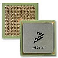
MSC8113TVT3600V Freescale Semiconductor, MSC8113TVT3600V Datasheet - Page 26

MSC8113TVT3600V
Manufacturer Part Number
MSC8113TVT3600V
Description
DSP TRI-CORE 431-FCPBGA
Manufacturer
Freescale Semiconductor
Series
MSC81xx StarCorer
Type
SC140 Corer
Datasheet
1.MSC8113TMP3600V.pdf
(44 pages)
Specifications of MSC8113TVT3600V
Interface
Ethernet, I²C, TDM, UART
Clock Rate
300MHz
Non-volatile Memory
External
On-chip Ram
1.436MB
Voltage - I/o
3.30V
Voltage - Core
1.10V
Operating Temperature
-40°C ~ 105°C
Mounting Type
Surface Mount
Package / Case
431-FCPBGA
Svhc
No SVHC (15-Dec-2010)
Base Number
8113
Cache On Chip L1/l2 Memory
64KB
Core Frequency Typ
300MHz
Dsp Type
Tri Core
External Supported Memory
SRAM, SDRAM
Interface Type
TDM, I2C, UART,
Rohs Compliant
Yes
Lead Free Status / RoHS Status
Lead free / RoHS Compliant
Available stocks
Company
Part Number
Manufacturer
Quantity
Price
Company:
Part Number:
MSC8113TVT3600V
Manufacturer:
Freescale Semiconductor
Quantity:
10 000
Electrical Characteristics
2.5.6
The timings in the following sections are based on a 20 pF capacitive load.
2.5.6.1
26
Notes:
No.
100
101
102
103
104
105
106
107
108
109
110
111
112
201
202
Attributes
Attributes
Read/Write data strobe deassertion width:
•
•
Read data strobe deassertion to output data high impedance
Read data strobe assertion to output data active from high impedance
Output data hold time after read data strobe deassertion
Read/Write data strobe assertion to HTA active from high impedance
Output data valid to HTA assertion
Read/Write data strobe assertion to HTA valid
Read/Write data strobe deassertion to output HTA high impedance.
(DCR[HTAAD] = 0, HTA at end of access released at logic 0)
Read/Write data strobe deassertion to output HTA deassertion.
(DCR[HTAAD] = 1, HTA at end of access released at logic 1)
Read/Write data strobe deassertion to output HTA high impedance.
(DCR[HTAAD] = 1, HTA at end of access released at logic 1
•
•
•
Read/Write data strobe assertion width
Host data input set-up time before write data strobe deassertion
Host data input hold time after write data strobe deassertion
1.
2.
3.
DCR[HTAAD] = 1
— Consecutive access to the same DSI
— Different device with DCR[HTADT] = 01
— Different device with DCR[HTADT] = 10
— Different device with DCR[HTADT] = 11
DCR[HTAAD] = 0
DCR[HTADT] = 01
DCR[HTADT] = 10
DCR[HTADT] = 11
DSI Timing
Attributes refers to the following signals: HCS, HA[11–29], HCID[0–4], HDST, HRW, HRDS, and HWBSn.
This specification is tested in dual-strobe mode. Timing in single-strobe mode is guaranteed by design.
All values listed in this table are tested or guaranteed by design.
DSI Asynchronous Mode
1
1
set-up time before strobe (HWBS[n]) assertion
hold time after data strobe deassertion
DACK/DONE/DRACK
MSC8113 Tri-Core Digital Signal Processor Data Sheet, Rev. 1
Characteristics
Table 18. DSI Asynchronous Mode Timing
REFCLK
DONE
DREQ
Figure 13. DMA Signals
2
39
41
37
40
5 + (1.5 × T
5 + (2.5 × T
1.8 + T
1.8 + T
1.8 + T
5 + T
Min
1.5
1.3
2.0
2.2
2.2
3.2
1.0
1.7
—
—
—
—
—
REFCLK
REFCLK
REFCLK
REFCLK
REFCLK
REFCLK
38
)
)
5 + (1.5 × T
5 + (2.5 × T
Freescale Semiconductor
5 + T
Max
8.5
7.4
6.5
6.5
—
—
—
—
—
—
—
—
—
—
REFCLK
REFCLK
REFCLK
)
)
Unit
ns
ns
ns
ns
ns
ns
ns
ns
ns
ns
ns
ns
ns
ns
ns
ns
ns
ns
ns
ns
ns


