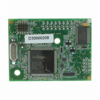
20-101-1105 Rabbit Semiconductor, 20-101-1105 Datasheet - Page 21

20-101-1105
Manufacturer Part Number
20-101-1105
Description
MODULE RCM4100 RABBITCORE
Manufacturer
Rabbit Semiconductor
Datasheet
1.20-101-1093.pdf
(112 pages)
Specifications of 20-101-1105
Module/board Type
MPU Core Module
Data Bus Width
8 bit
For Use With/related Products
RCM4100
Lead Free Status / RoHS Status
Lead free / RoHS Compliant
Other names
316-1121
- Current page: 21 of 112
- Download datasheet (2Mb)
•
•
•
Once you have loaded and executed these five programs and have an understanding of
how Dynamic C and the RCM4100 series of modules interact, you can move on and try
the other sample programs, or begin building your own.
User’s Manual
LOW_POWER.C
consumption by the Rabbit microprocessor. There are four features that lead to the low-
est possible power draw by the microprocessor.
Once you are ready to compile and run this sample program, use
just
once the target starts running off the 32 kHz oscillator.
This sample program will toggle LEDs DS2 and DS3 on the Prototyping Board. You
may use an oscilloscope. DS2 will blink the fastest. After switching to low power, both
LEDs will blink together.
TAMPERDETECTION.C
mode. When an attempt is detected, the battery-backed onchip-encryption RAM on the
Rabbit 4000 is erased. This battery-backed onchip-encryption RAM can be useful to
store data such as an AES encryption key from a remote location.
This sample program shows how to load and read the battery-backed onchip-encryption
RAM and how to enable a visual indicator.
Once this sample is compiled running (you have pressed the
program is open), remove the programming cable and press the reset button on the
Prototyping Board to reset the module. LEDs DS2 and DS3 will be flashing on and off.
Now press switch S2 to load the battery-backed RAM with the encryption key. The
LEDs are now on continuously. Notice that the LEDs will stay on even when you press
the reset button on the Prototyping Board.
Reconnect the programming cable briefly and unplug it again. The LEDs will be flash-
ing because the battery-backed onchip-encryption RAM has been erased. Notice that
the LEDs will continue flashing even when you press the reset button on the Prototyp-
ing Board.
You may press switch S2 again and repeat the last steps to watch the LEDs.
TOGGLESWITCH.C
using the press-and-release method of debouncing. LEDs DS2 and DS3 on the Proto-
typing Board are turned on and off when you press switches S2 and S3. S2 and S3 are
controlled by PB4 and PB5 respectively.
1. Run the CPU from the 32 kHz crystal.
2. Turn off the high-frequency crystal oscillator.
3. Run from RAM.
4. Ensure that internal I/O instructions do not use CS0.
F9
. This will disable polling, which will allow Dynamic C to continue debugging
—demonstrates how to implement a function in RAM to reduce power
—demonstrates the use of costatements to detect switch presses
—demonstrates how to detect an attempt to enter the bootstrap
F9
key while the sample
<Alt-F9>
instead of
17
Related parts for 20-101-1105
Image
Part Number
Description
Manufacturer
Datasheet
Request
R

Part Number:
Description:
COMPUTER SGL-BRD BL2500 29.4MHZ
Manufacturer:
Rabbit Semiconductor
Datasheet:

Part Number:
Description:
COMPUTER SGL-BRD BL2500 29.4MHZ
Manufacturer:
Rabbit Semiconductor
Datasheet:

Part Number:
Description:
DISPLAY GRAPHIC 12KEY PROG OP670
Manufacturer:
Rabbit Semiconductor
Datasheet:

Part Number:
Description:
DISPLAY GRAPHIC 12KEY ETH OP6700
Manufacturer:
Rabbit Semiconductor
Datasheet:

Part Number:
Description:
COMPUTER SINGLE-BOARD BL2030
Manufacturer:
Rabbit Semiconductor

Part Number:
Description:
COMPUTER SGL-BOARD ETH BL2010
Manufacturer:
Rabbit Semiconductor

Part Number:
Description:
MODULE OP6810 W/O ETH/MEM EXPANS
Manufacturer:
Rabbit Semiconductor
Datasheet:

Part Number:
Description:
COMPUTER SINGLE-BOARD BL2020
Manufacturer:
Rabbit Semiconductor

Part Number:
Description:
COMPUTER BL2010 W/FRICTION LOCK
Manufacturer:
Rabbit Semiconductor

Part Number:
Description:
COMPUTER BL2020 W/FRICTION LOCK
Manufacturer:
Rabbit Semiconductor

Part Number:
Description:
COMPUTER SGL-BRD BL2500 44.2MHZ
Manufacturer:
Rabbit Semiconductor
Datasheet:

Part Number:
Description:
COMPUTER SGL-BOARD FULL BL2000
Manufacturer:
Rabbit Semiconductor

Part Number:
Description:
COMPUTER SINGLE-BOARD BL2110
Manufacturer:
Rabbit Semiconductor

Part Number:
Description:
COMPUTER SGL-BRD 29.4MHZ BL2610
Manufacturer:
Rabbit Semiconductor
Datasheet:

Part Number:
Description:
INTERFACE OP6800 512K FLASH&SRAM
Manufacturer:
Rabbit Semiconductor
Datasheet:


