20-101-1105 Rabbit Semiconductor, 20-101-1105 Datasheet - Page 36
20-101-1105
Manufacturer Part Number
20-101-1105
Description
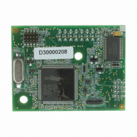
MODULE RCM4100 RABBITCORE
Manufacturer
Rabbit Semiconductor
Datasheet
1.20-101-1093.pdf
(112 pages)
Specifications of 20-101-1105
Module/board Type
MPU Core Module
Data Bus Width
8 bit
For Use With/related Products
RCM4100
Lead Free Status / RoHS Status
Lead free / RoHS Compliant
Other names
316-1121


4.1.1 Memory I/O Interface
The Rabbit 4000 address lines (A0–A19) and all the data lines (D0–D7) are routed inter-
nally to the onboard flash memory and SRAM chips. I/0 write (/IOWR) and I/0 read
(/IORD) are available for interfacing to external devices.
Parallel Port A can also be used as an external I/O data bus to isolate external I/O from the
main data bus. Parallel Port B pins PB2–PB7 can also be used as an auxiliary address bus.
When using the auxiliary I/O bus for any reason, you must add the following line at the
beginning of your program.
Selected pins on Parallel Ports D and E as specified in Table 2 may be used for input
capture, quadrature decoder, DMA, and pulse-width modulator purposes.
4.1.2 Other Inputs and Outputs
The status and the two SMODE pins, SMODE0 and SMODE1, can be brought out to
header J2 instead of PE5–PE7 as explained in Appendix A.5.
/RESET_IN is normally associated with the programming port, but may be used as an
external input to reset the Rabbit 4000 microprocessor and the module memory.
/RESET_OUT is an output from the reset circuitry that can be used to reset other
peripheral devices.
32
40–47
48
49
50
Pin
#define PORTA_AUX_IO
LN[0:7]
CONVERT/n.c. Digital Input
VREF/n.c.
GND
Pin Name
Table 2. RCM4100 Series Pinout Configurations (continued)
Analog Input
Analog reference
voltage
Ground
Default Use
// required to enable auxiliary I/O bus
Alternate Use
A/D converter
(RCM4100 only)
1.15 V/2.048 V/2.500 V
on-chip ref. voltage
(RCM4100 only)
RabbitCore RCM4100
Notes
Related parts for 20-101-1105
Image
Part Number
Description
Manufacturer
Datasheet
Request
R

Part Number:
Description:
COMPUTER SGL-BRD BL2500 29.4MHZ
Manufacturer:
Rabbit Semiconductor
Datasheet:

Part Number:
Description:
COMPUTER SGL-BRD BL2500 29.4MHZ
Manufacturer:
Rabbit Semiconductor
Datasheet:

Part Number:
Description:
DISPLAY GRAPHIC 12KEY PROG OP670
Manufacturer:
Rabbit Semiconductor
Datasheet:
Part Number:
Description:
DISPLAY GRAPHIC 12KEY ETH OP6700
Manufacturer:
Rabbit Semiconductor
Datasheet:

Part Number:
Description:
COMPUTER SINGLE-BOARD BL2030
Manufacturer:
Rabbit Semiconductor
Part Number:
Description:
COMPUTER SGL-BOARD ETH BL2010
Manufacturer:
Rabbit Semiconductor

Part Number:
Description:
MODULE OP6810 W/O ETH/MEM EXPANS
Manufacturer:
Rabbit Semiconductor
Datasheet:
Part Number:
Description:
COMPUTER SINGLE-BOARD BL2020
Manufacturer:
Rabbit Semiconductor
Part Number:
Description:
COMPUTER BL2010 W/FRICTION LOCK
Manufacturer:
Rabbit Semiconductor
Part Number:
Description:
COMPUTER BL2020 W/FRICTION LOCK
Manufacturer:
Rabbit Semiconductor
Part Number:
Description:
COMPUTER SGL-BRD BL2500 44.2MHZ
Manufacturer:
Rabbit Semiconductor
Datasheet:
Part Number:
Description:
COMPUTER SGL-BOARD FULL BL2000
Manufacturer:
Rabbit Semiconductor

Part Number:
Description:
COMPUTER SINGLE-BOARD BL2110
Manufacturer:
Rabbit Semiconductor

Part Number:
Description:
COMPUTER SGL-BRD 29.4MHZ BL2610
Manufacturer:
Rabbit Semiconductor
Datasheet:
Part Number:
Description:
INTERFACE OP6800 512K FLASH&SRAM
Manufacturer:
Rabbit Semiconductor
Datasheet: