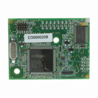
20-101-1105 Rabbit Semiconductor, 20-101-1105 Datasheet - Page 4

20-101-1105
Manufacturer Part Number
20-101-1105
Description
MODULE RCM4100 RABBITCORE
Manufacturer
Rabbit Semiconductor
Datasheet
1.20-101-1093.pdf
(112 pages)
Specifications of 20-101-1105
Module/board Type
MPU Core Module
Data Bus Width
8 bit
For Use With/related Products
RCM4100
Lead Free Status / RoHS Status
Lead free / RoHS Compliant
Other names
316-1121
Chapter 5. Software Reference
Appendix A. RCM4100 Specifications
Appendix B. Prototyping Board
Appendix C. Power Supply
Index
Schematics
4.5 Other Hardware .................................................................................................................................. 41
4.6 Memory .............................................................................................................................................. 42
5.1 More About Dynamic C ..................................................................................................................... 43
5.2 Dynamic C Function Calls ................................................................................................................ 45
5.3 Upgrading Dynamic C ....................................................................................................................... 66
A.1 Electrical and Mechanical Characteristics ........................................................................................ 68
A.2 Rabbit 4000 DC Characteristics ........................................................................................................ 74
A.3 I/O Buffer Sourcing and Sinking Limit............................................................................................. 75
A.4 Bus Loading ...................................................................................................................................... 75
A.5 Jumper Configurations ...................................................................................................................... 78
A.6 Conformal Coating ............................................................................................................................ 80
B.1 Introduction ....................................................................................................................................... 82
B.2 Mechanical Dimensions and Layout ................................................................................................. 85
B.3 Power Supply..................................................................................................................................... 86
B.4 Using the Prototyping Board ............................................................................................................. 87
B.5 Prototyping Board Jumper Configurations........................................................................................ 95
C.1 Power Supplies .................................................................................................................................. 99
4.5.1 Clock Doubler ............................................................................................................................ 41
4.5.2 Spectrum Spreader...................................................................................................................... 41
4.6.1 SRAM......................................................................................................................................... 42
4.6.2 Flash EPROM............................................................................................................................. 42
5.2.1 Digital I/O................................................................................................................................... 45
5.2.2 Serial Communication Drivers ................................................................................................... 45
5.2.3 SRAM Use.................................................................................................................................. 45
5.2.4 Prototyping Board Function Calls .............................................................................................. 47
5.2.5 Analog Inputs (RCM4100 only)................................................................................................. 49
5.3.1 Add-On Modules ........................................................................................................................ 66
A.1.1 A/D Converter ........................................................................................................................... 72
A.1.2 Headers ...................................................................................................................................... 73
B.1.1 Prototyping Board Features ....................................................................................................... 83
B.4.1 Adding Other Components ........................................................................................................ 89
B.4.2 Measuring Current Draw ........................................................................................................... 89
B.4.3 Analog Features (RCM4100 only) ............................................................................................ 90
B.4.4 Serial Communication ............................................................................................................... 93
C.1.1 Battery Backup .......................................................................................................................... 99
C.1.2 Battery-Backup Circuit ............................................................................................................ 100
C.1.3 Reset Generator........................................................................................................................ 100
5.2.4.1 Board Initialization ............................................................................................................ 47
5.2.4.2 Alerts.................................................................................................................................. 48
B.4.3.1 A/D Converter Inputs........................................................................................................ 90
B.4.3.2 Thermistor Input ............................................................................................................... 92
B.4.3.3 A/D Converter Calibration................................................................................................ 92
B.4.4.1 RS-232 .............................................................................................................................. 94
RabbitCore RCM4100
103
107
43
67
81
99


