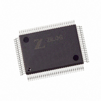
Z8018110FEG Zilog, Z8018110FEG Datasheet - Page 15

Z8018110FEG
Manufacturer Part Number
Z8018110FEG
Description
IC 10MHZ ACCESS CTRL 100-QFP
Manufacturer
Zilog
Datasheet
1.Z8018110FEG.pdf
(74 pages)
Specifications of Z8018110FEG
Processor Type
Z180
Features
Smart Access Controller SAC™
Speed
10MHz
Voltage
5V
Mounting Type
Surface Mount
Package / Case
100-QFP
Processor Series
Z8018xx
Core
Z80
Data Bus Width
8 bit
Program Memory Type
ROMLess
Program Memory Size
1 MB
Interface Type
ASCI, UART
Maximum Clock Frequency
10 MHz
Number Of Programmable I/os
16
Number Of Timers
2
Operating Supply Voltage
4.5 V to 5.5 V
Maximum Operating Temperature
+ 100 C
Mounting Style
SMD/SMT
Development Tools By Supplier
Z8018100ZCO
Minimum Operating Temperature
- 40 C
Lead Free Status / RoHS Status
Lead free / RoHS Compliant
Other names
269-4692
Z8018110FEG
Z8018110FEG
Available stocks
Company
Part Number
Manufacturer
Quantity
Price
Company:
Part Number:
Z8018110FEG
Manufacturer:
Zilog
Quantity:
340
Part Number:
Z8018110FEG
Manufacturer:
ZELOG
Quantity:
20 000
Zilog
Each of the Counter/Timer Channels, designated Chan-
nels 0-3, have an 8-bit prescaler (when used in timer
mode) and its own 8-bit counter to provide a wide range of
count resolution. Each of the channels have their own
Clock/Trigger input to quantify the counting process and
an output to indicate zero crossing/timeout conditions.
Parallel Interface Adapter (PIA)
The SAC has two 8-bit Parallel Interface Adapter (PIA)
Ports. The ports are referred to as PIA1 and PIA2. Each port
has two associated control registers; a Data Register and
a register to determine each bit’s direction (input or out-
put). PIA1 is multiplexed with the CTC I/O pins. When the
CTC I/O feature is selected, the CTC I/O functions override
the PIA1 feature. Mode Selection is made through the
System Configuration Register (Address: EDh; Bit D0).
PIA1 has Schmitt-triggered inputs to have a better noise
margin. These ports are inputs after reset.
Clock Generator
The SAC uses the Z181 MPU’s on-chip clock generator to
supply system clock. The required clock is easily gener-
ated by connecting a crystal to the external terminals
(XTAL, EXTAL). The clock output runs at half the crystal
frequency. The system clock inputs of the SCC and the
CTC are internally connected to the PHI output of the Z181
MPU.
DS971800500
Control
Data
CPU
BUS
I/O
Figure 5. CTC Block Diagram
PS009701-0301
/RESET
Interrupt
Counter/
Internal
Control
These signals are multiplexed with the Parallel Interface
Adapter 1 (PIA1). With only one interrupt vector pro-
grammed into the logic unit, each channel can generate a
unique interrupt vector in response to the interrupt ac-
knowledge cycle.
Timer
Logic
Logic
Logic
Figure 6. Circuit Configuration For Crystal
EXTAL
Crystal
Inputs
XTAL
4
4
/INT
IEI
IEO
ZC/TO
CLK/TRG
Mutiplexed
with PIA1
S
MART
C1
C2
A
CCESS
C
ONTROLLER
Z80181
2-15
SAC
™


