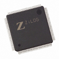
EZ80190AZ050EG Zilog, EZ80190AZ050EG Datasheet - Page 29

EZ80190AZ050EG
Manufacturer Part Number
EZ80190AZ050EG
Description
IC WEBSERVER 50MHZ XTEMP 100LQFP
Manufacturer
Zilog
Datasheet
1.EZ80190AZ050SG.pdf
(221 pages)
Specifications of EZ80190AZ050EG
Processor Type
eZ80
Features
High Speed, Single-Cycle Instruction-Fetch
Speed
50MHz
Voltage
3.3V
Mounting Type
Surface Mount
Package / Case
100-LQFP
Processor Series
EZ80190x
Core
eZ80
Data Bus Width
8 bit
Program Memory Type
ROMLess
Data Ram Size
8 KB
Interface Type
I2C, IrDA, SPI, UART
Maximum Clock Frequency
50 MHz
Number Of Programmable I/os
32
Number Of Timers
6
Operating Supply Voltage
3 V to 3.6 V
Maximum Operating Temperature
+ 70 C
Mounting Style
SMD/SMT
Minimum Operating Temperature
0 C
Lead Free Status / RoHS Status
Lead free / RoHS Compliant
Other names
269-3865
EZ80190AZ050EG
EZ80190AZ050EG
Available stocks
Company
Part Number
Manufacturer
Quantity
Price
Company:
Part Number:
EZ80190AZ050EG
Manufacturer:
TYCO
Quantity:
120
Company:
Part Number:
EZ80190AZ050EG
Manufacturer:
Zilog
Quantity:
70
- Current page: 29 of 221
- Download datasheet (4Mb)
Table 1. 100-Pin LQFP Pin Identification of the eZ80190 Device (Continued)
PS006614-1208
Pin
No.
79
80
81
Symbol
PD3
SS0
CTS0
PD4
DTR0
PD5
DSR0
Function
GPIO Port D
Slave Select
Clear to Send
GPIO Port D
Data Terminal
Ready
GPIO Port D
Data Set
Ready
Signal Direction
Input/Output
Input, Active Low
Input, Active Low
Input/Output
Output, Active Low The DTR0 pin carries the modem control signal to
Input/Output
Input, Active Low
Description
The PD3 pin can be used for GPIO. It can be
individually programmed as an input or output
and can also be used individually as an interrupt
input. Each Port D pin, when programmed as an
output, can be selected to be an open-drain or
open-source output. Port D is multiplexed with
one channel of the UZI interface.
The slave select input line is used to select a
slave device in SPI mode. This signal is
multiplexed with PD3.
The CTS0 pin carries the modem status signal to
the UART. This signal is multiplexed with PD3.
The PD4 pin can be used for GPIO. It can be
individually programmed as an input or output
and can also be used individually as an interrupt
input. Each Port D pin, when programmed as an
output, can be selected to be an open-drain or
open-source output. Port D is multiplexed with
one channel of the UZI interface.
the UART. This signal is multiplexed with PD4.
The PD5 pin can be used for GPIO. It can be
individually programmed as an input or output
and can also be used individually as an interrupt
input. Each Port D pin, when programmed as an
output, can be selected to be an open-drain or
open-source output. Port D is multiplexed with
one channel of the UZI interface.
The DSR0 pin carries the modem status signal to
the UART. This signal is multiplexed with PC5
and PD5.
Product Specification
Architectural Overview
19
Related parts for EZ80190AZ050EG
Image
Part Number
Description
Manufacturer
Datasheet
Request
R

Part Number:
Description:
Communication Controllers, ZILOG INTELLIGENT PERIPHERAL CONTROLLER (ZIP)
Manufacturer:
Zilog, Inc.
Datasheet:

Part Number:
Description:
KIT DEV FOR Z8 ENCORE 16K TO 64K
Manufacturer:
Zilog
Datasheet:

Part Number:
Description:
KIT DEV Z8 ENCORE XP 28-PIN
Manufacturer:
Zilog
Datasheet:

Part Number:
Description:
DEV KIT FOR Z8 ENCORE 8K/4K
Manufacturer:
Zilog
Datasheet:

Part Number:
Description:
KIT DEV Z8 ENCORE XP 28-PIN
Manufacturer:
Zilog
Datasheet:

Part Number:
Description:
DEV KIT FOR Z8 ENCORE 4K TO 8K
Manufacturer:
Zilog
Datasheet:

Part Number:
Description:
CMOS Z8 microcontroller. ROM 16 Kbytes, RAM 256 bytes, speed 16 MHz, 32 lines I/O, 3.0V to 5.5V
Manufacturer:
Zilog, Inc.
Datasheet:

Part Number:
Description:
Low-cost microcontroller. 512 bytes ROM, 61 bytes RAM, 8 MHz
Manufacturer:
Zilog, Inc.
Datasheet:

Part Number:
Description:
Z8 4K OTP Microcontroller
Manufacturer:
Zilog, Inc.
Datasheet:

Part Number:
Description:
CMOS SUPER8 ROMLESS MCU
Manufacturer:
Zilog, Inc.
Datasheet:

Part Number:
Description:
SL1866 CMOSZ8 OTP Microcontroller
Manufacturer:
Zilog, Inc.
Datasheet:

Part Number:
Description:
SL1866 CMOSZ8 OTP Microcontroller
Manufacturer:
Zilog, Inc.
Datasheet:

Part Number:
Description:
OTP (KB) = 1, RAM = 125, Speed = 12, I/O = 14, 8-bit Timers = 2, Comm Interfaces Other Features = Por, LV Protect, Voltage = 4.5-5.5V
Manufacturer:
Zilog, Inc.
Datasheet:

Part Number:
Description:
Manufacturer:
Zilog, Inc.
Datasheet:


