MPC8544VTALF Freescale Semiconductor, MPC8544VTALF Datasheet - Page 105
MPC8544VTALF
Manufacturer Part Number
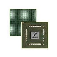
MPC8544VTALF
Description
MPU POWERQUICC III 783-PBGA
Manufacturer
Freescale Semiconductor
Datasheets
1.MPC8544VTALF.pdf
(117 pages)
2.MPC8544VTALF.pdf
(2 pages)
3.MPC8544VTALF.pdf
(1340 pages)
Specifications of MPC8544VTALF
Processor Type
MPC85xx PowerQUICC III 32-Bit
Speed
667MHz
Voltage
1V
Mounting Type
Surface Mount
Package / Case
783-FCPBGA
Processor Series
MPC85xx
Core
e500
Data Bus Width
32 bit
Maximum Clock Frequency
667 MHz
Maximum Operating Temperature
+ 105 C
Mounting Style
SMD/SMT
Data Ram Size
32 KB
I/o Voltage
1.8 V, 3.3 V
Interface Type
I2C, HSSI, DUART
Minimum Operating Temperature
0 C
Lead Free Status / RoHS Status
Lead free / RoHS Compliant
Features
-
Lead Free Status / Rohs Status
Lead free / RoHS Compliant
Available stocks
Company
Part Number
Manufacturer
Quantity
Price
Company:

Part Number:
MPC8544VTALF
Manufacturer:
Freescale Semiconductor
Quantity:
10 000
Company:
Part Number:
MPC8544VTALFA
Manufacturer:
Freescale Semiconductor
Quantity:
10 000


where:
The ratio of I
Solving for T, the equation becomes:
21 System Design Information
This section provides electrical and thermal design recommendations for successful application of the
MPC8544E.
21.1
This device includes six PLLs:
Freescale Semiconductor
•
•
•
•
•
I
I
V
V
V
V
I
I
q = Charge of electron (1.6 × 10
n = Ideality factor (normally 1.0)
K = Boltzman’s constant (1.38 × 10
T = Temperature (Kelvins)
The platform PLL generates the platform clock from the externally supplied SYSCLK input. The
frequency ratio between the platform and SYSCLK is selected using the platform PLL ratio
configuration bits as described in
The e500 core PLL generates the core clock as a slave to the platform clock. The frequency ratio
between the e500 core clock and the platform clock is selected using the e500 PLL ratio
configuration bits as described in
The PCI PLL generates the clocking for the PCI bus.
The local bus PLL generates the clock for the local bus.
There are two PLLs for the SerDes block.
fw
s
H
L
d
f
H
L
System Clocking
= Smaller diode bias current
= Saturation current
= Larger diode bias current
= Voltage forward biased
= Voltage at diode
= Forward current
= Diode voltage while I
= Diode voltage while I
H
V
to I
nT =
H
MPC8544E PowerQUICC III Integrated Processor Hardware Specifications, Rev. 5
– V
L
is usually selected to be 10:1. The above simplifies to the following:
1.986 × 10
L
V
= 1.986 × 10
H
– V
L
–4
L
H
is flowing
–4
is flowing
× nT
–19
Section 19.2, “CCB/SYSCLK PLL Ratio.”
Section 19.3, “e500 Core PLL Ratio.”
–23
C)
Joules/K)
System Design Information
105
Related parts for MPC8544VTALF
Image
Part Number
Description
Manufacturer
Datasheet
Request
R

Part Number:
Description:
Manufacturer:
Freescale Semiconductor, Inc
Datasheet:
Part Number:
Description:
Manufacturer:
Freescale Semiconductor, Inc
Datasheet:
Part Number:
Description:
Manufacturer:
Freescale Semiconductor, Inc
Datasheet:
Part Number:
Description:
Manufacturer:
Freescale Semiconductor, Inc
Datasheet:
Part Number:
Description:
Manufacturer:
Freescale Semiconductor, Inc
Datasheet:
Part Number:
Description:
Manufacturer:
Freescale Semiconductor, Inc
Datasheet:
Part Number:
Description:
Manufacturer:
Freescale Semiconductor, Inc
Datasheet:
Part Number:
Description:
Manufacturer:
Freescale Semiconductor, Inc
Datasheet:
Part Number:
Description:
Manufacturer:
Freescale Semiconductor, Inc
Datasheet:
Part Number:
Description:
Manufacturer:
Freescale Semiconductor, Inc
Datasheet:
Part Number:
Description:
Manufacturer:
Freescale Semiconductor, Inc
Datasheet:
Part Number:
Description:
Manufacturer:
Freescale Semiconductor, Inc
Datasheet:
Part Number:
Description:
Manufacturer:
Freescale Semiconductor, Inc
Datasheet:
Part Number:
Description:
Manufacturer:
Freescale Semiconductor, Inc
Datasheet:
Part Number:
Description:
Manufacturer:
Freescale Semiconductor, Inc
Datasheet: