MPC8544VTALF Freescale Semiconductor, MPC8544VTALF Datasheet - Page 92
MPC8544VTALF
Manufacturer Part Number
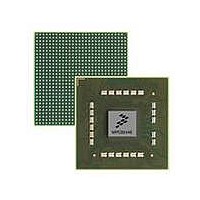
MPC8544VTALF
Description
MPU POWERQUICC III 783-PBGA
Manufacturer
Freescale Semiconductor
Datasheets
1.MPC8544VTALF.pdf
(117 pages)
2.MPC8544VTALF.pdf
(2 pages)
3.MPC8544VTALF.pdf
(1340 pages)
Specifications of MPC8544VTALF
Processor Type
MPC85xx PowerQUICC III 32-Bit
Speed
667MHz
Voltage
1V
Mounting Type
Surface Mount
Package / Case
783-FCPBGA
Processor Series
MPC85xx
Core
e500
Data Bus Width
32 bit
Maximum Clock Frequency
667 MHz
Maximum Operating Temperature
+ 105 C
Mounting Style
SMD/SMT
Data Ram Size
32 KB
I/o Voltage
1.8 V, 3.3 V
Interface Type
I2C, HSSI, DUART
Minimum Operating Temperature
0 C
Lead Free Status / RoHS Status
Lead free / RoHS Compliant
Features
-
Lead Free Status / Rohs Status
Lead free / RoHS Compliant
Available stocks
Company
Part Number
Manufacturer
Quantity
Price
Company:

Part Number:
MPC8544VTALF
Manufacturer:
Freescale Semiconductor
Quantity:
10 000
Company:
Part Number:
MPC8544VTALFA
Manufacturer:
Freescale Semiconductor
Quantity:
10 000


Package Description
92
10.This output is actively driven during reset rather than being three-stated during reset.
11.These JTAG pins have weak internal pull-up P-FETs that are always enabled.
12.These pins are connected to the V
13.Anode and cathode of internal thermal diode.
14.Treat pins AC7, T5, V2, and M7 as spare configuration pins cfg_spare[0:3]. The spare pins are unused POR config pins. It
15.If this pin is connected to a device that pulls down during reset, an external pull-up is required to drive this pin to a safe state
16.This pin is only an output in FIFO mode when used as Rx flow control.
17.Do not connect.
18.These are test signals for factory use only and must be pulled up (100 Ω to 1 kΩ) to OV
19.Independent supplies derived from board V
20.Recommend a pull-up resistor (1 K~) be placed on this pin to OV
21.The following pins must not be pulled down during power-on reset: HRESET_REQ, TRIG_OUT/READY/QUIESCE,
22.This pin requires an external 4.7-kΩ pull-down resistor to prevent PHY from seeing a valid transmit enable before it is actively
23.General-purpose POR configuration of user system.
24.When a PCI block is disabled, either the POR config pin that selects between internal and external arbiter must be pulled
25.MDIC0 is grounded through an 18.2-Ω precision 1% resistor and MDIC1 is connected GV
26.For SGMII mode.
27.Connect to GND.
28.For systems that boot from a local bus (GPCM)-controlled flash, a pull-up on LGPL4 is required.
6.The value of LA[28:31] during reset sets the CCB clock to SYSCLK PLL ratio. These pins require 4.7-kΩ pull-up or pull-down
7.The value of LALE, LGPL2, and LBCTL at reset set the e500 core clock to CCB clock PLL ratio. These pins require 4.7-kΩ
8.Functionally, this pin is an output, but structurally it is an I/O because it either samples configuration input during reset or
9.For proper state of these signals during reset, DMA_DACK[1] must be pulled down to GND through a resistor. DMA_DACK[0]
resistors. See
pull-up or pull-down resistors. See
because it has other manufacturing test functions. Therefore, this pin will be described as an I/O for boundary scan.
can be pulled up or left without a resistor. However, if there is any device on the net which might pull down the value of the
net at reset, then a pullup is needed on DMA_DACK[0].
and regulation.
is highly recommended that the customer provide the capability of setting these pins low (that is, pull-down resistor which
is not currently stuffed) in order to support new config options should they arise between revisions.
during reset.
MSRCID[2:4], and ASLEEP.
driven.
down to select external arbiter if there is any other PCI device connected on the PCI bus, or leave the address pins as No
Connect or terminated through 2–10 kΩ pull-up resistors with the default of internal arbiter if the address pins are not
connected to any other PCI device. The PCI block will drive the address pins if it is configured to be the PCI arbiter—through
POR config pins—irrespective of whether it is disabled via the DEVDISR register or not. It may cause contention if there is
any other PCI device connected on the bus.
1% resistor. These pins are used for automatic calibration of the DDR IOs.
Signal
Section 19.2, “CCB/SYSCLK PLL Ratio.”
MPC8544E PowerQUICC III Integrated Processor Hardware Specifications, Rev. 5
Table 62. MPC8544E Pinout Listing (continued)
DD
Section 19.3, “e500 Core PLL Ratio.”
/GND planes internally and may be used by the core power supply to improve tracking
Package Pin Number
DD
.
DD
.
Pin Type
DD
DD
for normal machine operation.
through an 18.2-Ω precision
Supply
Freescale Semiconductor
Power
Notes
Related parts for MPC8544VTALF
Image
Part Number
Description
Manufacturer
Datasheet
Request
R

Part Number:
Description:
Manufacturer:
Freescale Semiconductor, Inc
Datasheet:
Part Number:
Description:
Manufacturer:
Freescale Semiconductor, Inc
Datasheet:
Part Number:
Description:
Manufacturer:
Freescale Semiconductor, Inc
Datasheet:
Part Number:
Description:
Manufacturer:
Freescale Semiconductor, Inc
Datasheet:
Part Number:
Description:
Manufacturer:
Freescale Semiconductor, Inc
Datasheet:
Part Number:
Description:
Manufacturer:
Freescale Semiconductor, Inc
Datasheet:
Part Number:
Description:
Manufacturer:
Freescale Semiconductor, Inc
Datasheet:
Part Number:
Description:
Manufacturer:
Freescale Semiconductor, Inc
Datasheet:
Part Number:
Description:
Manufacturer:
Freescale Semiconductor, Inc
Datasheet:
Part Number:
Description:
Manufacturer:
Freescale Semiconductor, Inc
Datasheet:
Part Number:
Description:
Manufacturer:
Freescale Semiconductor, Inc
Datasheet:
Part Number:
Description:
Manufacturer:
Freescale Semiconductor, Inc
Datasheet:
Part Number:
Description:
Manufacturer:
Freescale Semiconductor, Inc
Datasheet:
Part Number:
Description:
Manufacturer:
Freescale Semiconductor, Inc
Datasheet:
Part Number:
Description:
Manufacturer:
Freescale Semiconductor, Inc
Datasheet: