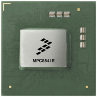
MPC8541EVTAQF Freescale Semiconductor, MPC8541EVTAQF Datasheet - Page 67

MPC8541EVTAQF
Manufacturer Part Number
MPC8541EVTAQF
Description
IC MPU POWERQUICC III 783-FCPBGA
Manufacturer
Freescale Semiconductor
Datasheet
1.MPC8541EVTALF.pdf
(88 pages)
Specifications of MPC8541EVTAQF
Processor Type
MPC85xx PowerQUICC III 32-Bit
Speed
1.0GHz
Voltage
1.3V
Mounting Type
Surface Mount
Package / Case
783-FCPBGA
Processor Series
MPC85xx
Core
e500
Data Bus Width
32 bit
Development Tools By Supplier
RDK-IDM-SBC
Maximum Clock Frequency
1000 MHz
Maximum Operating Temperature
+ 105 C
Mounting Style
SMD/SMT
I/o Voltage
2.5 V, 3.3 V
Minimum Operating Temperature
0 C
For Use With
MPC8548CDS - DEV TOOLS CDS FOR 8548CWH-PPC-8540N-VE - KIT EVAL SYSTEM MPC8540
Lead Free Status / RoHS Status
Lead free / RoHS Compliant
Features
-
Lead Free Status / Rohs Status
Lead free / RoHS Compliant
Available stocks
Company
Part Number
Manufacturer
Quantity
Price
Company:
Part Number:
MPC8541EVTAQF
Manufacturer:
Freescale Semiconductor
Quantity:
10 000
16 Thermal
This section describes the thermal specifications of the MPC8541E.
16.1
Table 49
Junction-to-ambient Natural Convection on four layer board (2s2p)
Junction-to-ambient (@200 ft/min or 1.0 m/s) on four layer board (2s2p)
Junction-to-ambient (@400 ft/min or 2.0 m/s) on four layer board (2s2p)
Junction-to-board thermal
Junction-to-case thermal
Notes
1. Junction temperature is a function of die size, on-chip power dissipation, package thermal resistance, mounting site (board)
2. Per JEDEC JESD51–6 with the board horizontal.
3. Thermal resistance between the die and the printed-circuit board per JEDEC JESD51-8. Board temperature is measured on
4. Thermal resistance between the die and the case top surface as measured by the cold plate method (MIL SPEC-883 Method
16.2
This section provides thermal management information for the flip chip plastic ball grid array (FC-PBGA)
package for air-cooled applications. Proper thermal control design is primarily dependent on the
system-level design—the heat sink, airflow, and thermal interface material. The recommended attachment
method to the heat sink is illustrated in
board with the spring force centered over the die. This spring force should not exceed 10 pounds force.
Freescale Semiconductor
temperature, ambient temperature, air flow, power dissipation of other components on the board, and board thermal
resistance
the top surface of the board near the package.
1012.1). Cold plate temperature is used for case temperature; measured value includes the thermal resistance of the
interface layer.
MPC8541E PowerQUICC™ III Integrated Communications Processor Hardware Specification, Rev. 4.2
provides the package thermal characteristics for the MPC8541E.
Thermal Characteristics
Thermal Management Information
Characteristic
Table 49. Package Thermal Characteristics
Figure
42. The heat sink should be attached to the printed-circuit
Symbol
R
R
R
R
R
θJMA
θJMA
θJMA
θJB
θJC
Value
0.96
17
14
13
10
°C/W
°C/W
°C/W
°C/W
°C/W
Unit
Notes
Thermal
1, 2
1, 2
1, 2
3
4
67


