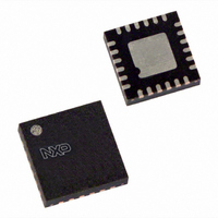
SC18IS600IBS,151 NXP Semiconductors, SC18IS600IBS,151 Datasheet - Page 14

SC18IS600IBS,151
Manufacturer Part Number
SC18IS600IBS,151
Description
IC SPI TO I2C BUS 24-HVQFN
Manufacturer
NXP Semiconductors
Datasheet
1.SC18IS600IBS151.pdf
(30 pages)
Specifications of SC18IS600IBS,151
Package / Case
24-VQFN Exposed Pad, 24-HVQFN, 24-SQFN, 24-DHVQFN
Controller Type
I²C Bus Controller
Interface
SPI
Voltage - Supply
2.4 V ~ 3.6 V
Current - Supply
11mA
Operating Temperature
-40°C ~ 85°C
Mounting Type
Surface Mount
Maximum Operating Frequency
12 MHz
Maximum Operating Temperature
+ 85 C
Minimum Operating Temperature
- 40 C
Mounting Style
SMD/SMT
Supply Voltage (max)
3.6 V
Supply Voltage (min)
2.4 V
Lead Free Status / RoHS Status
Lead free / RoHS Compliant
For Use With
568-3511 - DEMO BOARD SPI TO I2C
Lead Free Status / Rohs Status
Lead free / RoHS Compliant
Other names
568-4709
935286452151
SC18IS600IBS-S
935286452151
SC18IS600IBS-S
NXP Semiconductors
SC18IS600_601_5
Product data sheet
6.6.2 Read N bytes from I
6.6.3 I
6.6.4 Read buffer
Once the host issues this command, the SC18IS600/601 will start an I
transaction on the I
SC18IS600/601 will place this data in the receiver buffer, and will generate an interrupt on
the INT pin. The ‘transaction completed’ status can be read in the I2CStat. Note that the
data is not returned until a Read Buffer command is performed (see
buffer”).
Note that the third byte sent by the host is the device slave address. The SC18IS600/601
will ignore the least significant bit so a read will always be performed even if the least
significant bit is a ‘0’. The maximum number of bytes to be read is 96.
Once the host issues this command, the SC18IS600/601 will start a write transaction on
the I
will read data from the specified slave, place the data in the Receiver Buffer and generate
an interrupt on the INT pin. The ‘transaction completed’ status can be read in I2CStat.
Note that the data is not returned until a ‘Read Buffer’ command is performed.
2
Fig 14. Read N bytes from I
Fig 15. I
Fig 16. Read buffer
C-bus read after write
SPI host sends
COMMAND
2
C-bus to the specified slave address. Once the data is written, the SC18IS600/601
0x02
2
C-bus read after write
SPI host sends
COMMAND
SCLK
MOSI
NUMBER OF
0x01
CS
WRITE
BYTES
2
C-bus to the specified slave address. Once the data is received, the
OF BYTES
NUMBER
command 0x01
2
Rev. 05 — 28 July 2008
NUMBER OF
C-bus slave device
BYTES
READ
SPI host sends
2
COMMAND
C-bus slave device
0x06
SLAVE ADDRESS
ADDRESS
+ R
number of bytes D[7:0]
SLAVE
BYTE 1
+ W
DATA
WRITE
BYTE 0
DATA
BYTE N
002aab868
DATA
slave address A[7:1]
SC18IS600/601
SPI to I
BYTE N
WRITE
DATA
Section 6.6.4 “Read
2
© NXP B.V. 2008. All rights reserved.
C-bus read
002aab719
2
1
C-bus interface
ADDRESS
SLAVE
+ R
002aab720
14 of 30


