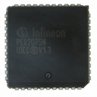
PEB2075N-V13TR Infineon Technologies, PEB2075N-V13TR Datasheet - Page 27

PEB2075N-V13TR
Manufacturer Part Number
PEB2075N-V13TR
Description
IC CONTROLLER D-CH EXCH 44-PLCC
Manufacturer
Infineon Technologies
Datasheet
1.PEB2075N-V13TR.pdf
(81 pages)
Specifications of PEB2075N-V13TR
Controller Type
Digital Exchange Controller
Interface
PCM
Voltage - Supply
4.75 V ~ 5.25 V
Current - Supply
10mA
Operating Temperature
0°C ~ 70°C
Mounting Type
Surface Mount
Package / Case
44-PLCC
Lead Free Status / RoHS Status
Contains lead / RoHS non-compliant
Other names
PEB2075N-V13INTR
PEB2075N-V13TR
PEB2075N-V13TR
Available stocks
Company
Part Number
Manufacturer
Quantity
Price
Company:
Part Number:
PEB2075N-V13TR
Manufacturer:
LT
Quantity:
512
Company:
Part Number:
PEB2075N-V13TR
Manufacturer:
Infineon Technologies
Quantity:
10 000
2.4.2 HDLC Communication Functions
Basic HDLC Functions
Each one of the four controller channels handles the following basic HDLC functions.
Receive direction
Transmit direction
Semiconductor Group
– Flag detection
– Zero delete
– Address recognition
– CRC checking
– Check for abort
– Check for idle
– Minimum length checking
– Flag generation
– Zero insert
– CRC generation
– Abort sequence generation
– Inter-frame time fill
A zero followed by six consecutive ones and another zero is recognized as a flag.
A zero after five consecutive ones within an HDLC frame is deleted.
A frame may be accepted or rejected on the basis of a comparison of the most significant
address byte (Service Access Point Identifier SAPI in Link Access Procedure for the D-
channel LAPD) with three fixed SAPI values.
The CRC field of an HDLC frame is checked according to the generator polynomial
x
Seven or more consecutive ones are interpreted as an abort sequence.
Fifteen or more consecutive ones are interpreted as "idle", and reported to the processor via
a status bit.
Reception of frames with less than three bytes between opening and closing flag is not
reported to the microcontroller.
A flag is generated at the beginning and at the end of every frame.
A zero is inserted after five consecutive ones within an HDLC frame.
The CRC field of the transmitted frame is generated according to the generator polynomial
x
An HDLC frame may be terminated with an abort sequence under software control or due to
a FIFO underrun condition.
As inter-frame time fill either flags or idle (continuous ones) may be transmitted.
16
16
+ x
+ x
12
12
+ x
+ x
5
5
+ 1.
+ 1.
27
Functional Description


