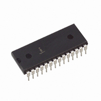
CP82C59A-12 Intersil, CP82C59A-12 Datasheet - Page 11

CP82C59A-12
Manufacturer Part Number
CP82C59A-12
Description
IC INTERFACE 5V 12.5MHZ 28-DIP
Manufacturer
Intersil
Datasheet
1.CS82C59AZ.pdf
(22 pages)
Specifications of CP82C59A-12
Controller Type
CMOS Priority Interrupt Controller
Voltage - Supply
4.5 V ~ 5.5 V
Current - Supply
1mA
Operating Temperature
0°C ~ 70°C
Mounting Type
Through Hole
Package / Case
28-DIP (0.600", 15.24mm)
Supply Voltage Range
4.5V To 5.5V
Supply Current
1mA
Digital Ic Case Style
DIP
No. Of Pins
28
Operating Temperature Range
0°C To +70°C
Filter Terminals
Through Hole
Rohs Compliant
No
Lead Free Status / RoHS Status
Contains lead / RoHS non-compliant
Interface
-
Available stocks
Company
Part Number
Manufacturer
Quantity
Price
Operation Command Words (OCWs)
After the Initialization Command Words (lCWs) are
programmed into the 82C59A, the device is ready to accept
interrupt requests at its input lines. However, during the
82C59A operation, a selection of algorithms can command
the 82C59A to operate in various modes through the
Operation Command Words (OCWs).
Operation Command Word 1 (OCW1)
OCW1 sets and clears the mask bits in the Interrupt Mask
Register (lMR) M7 - M0 represent the eight mask bits. M = 1
indicates the channel is masked (inhibited), M = 0 indicates
the channel is enabled.
Operation Command Word 2 (OCW2)
R, SL, EOI - These three bits control the Rotate and End of
Interrupt modes and combinations of the two. A chart of
these combinations can be found on the Operation
Command Word Format.
L2, L1, L0 - These bits determine the interrupt level acted
upon when the SL bit is active.
Operation Command Word 3 (OCW3)
ESMM - Enable Special Mask Mode. When this bit is set to 1
it enables the SMM bit to set or reset the Special Mask
Mode. When ESMM = 0, the SMM bit becomes a “don’t
care”.
SMM - Special Mask Mode. If ESMM = 1 and SMM = 1, the
82C59A will enter Special Mask Mode. If ESMM = 1 and
SMM = 0, the 82C59A will revert to normal mask mode.
When ESMM = 0, SMM has no effect.
Fully Nested Mode
This mode is entered after initialization unless another mode
is programmed. The interrupt requests are ordered in priority
from 0 through 7 (0 highest). When an interrupt is
acknowledged the highest priority request is determined and
its vector placed on the bus. Additionally, a bit of the Interrupt
Service register (IS0 - 7) is set. This bit remains set until the
microprocessor issues an End of Interrupt (EOI) command
immediately before returning from the service routine, or if
the AEOI (Automatic End of Interrupt) bit is set, until the
A0
1
0
0
M7
D7
R
0
OPERATION COMMAND WORDS (OCWs)
ESMM SMM
M6
D6
SL
EOI
D5
M5
OCW1
OCW2
OCW3
D4
M4
11
0
0
M3
D3
0
1
M2
D2
L2
P
M1
RR
D1
L1
RIS
M0
D0
L0
82C59A
82C59A
trailing edge of the last INTA. While the IS bit is set, all
further interrupts of the same or lower priority are inhibited,
while higher levels will generate an interrupt (which will be
acknowledged only if the microprocessor internal interrupt
enable flip-flop has been re-enabled through software).
After the initialization sequence, IR0 has the highest priority
and IR7 the lowest. Priorities can be changed, as will be
explained in the rotating priority mode or via the set priority
command.
March 17, 2006
FN2784.5


