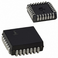
IS82C59A-12X96 Intersil, IS82C59A-12X96 Datasheet - Page 13

IS82C59A-12X96
Manufacturer Part Number
IS82C59A-12X96
Description
IC CTRLR INTERRPT 12.5MHZ 28PLCC
Manufacturer
Intersil
Datasheet
1.CS82C59AZ.pdf
(22 pages)
Specifications of IS82C59A-12X96
Controller Type
CMOS Priority Interrupt Controller
Voltage - Supply
4.5 V ~ 5.5 V
Current - Supply
1mA
Operating Temperature
-40°C ~ 85°C
Mounting Type
Surface Mount
Package / Case
28-PLCC
Lead Free Status / RoHS Status
Contains lead / RoHS non-compliant
Interface
-
Available stocks
Company
Part Number
Manufacturer
Quantity
Price
End of Interrupt (EOI)
The In-Service (IS) bit can be reset either automatically
following the trailing edge of the last in sequence INTA pulse
(when AEOI bit in lCW1 is set) or by a command word that
must be issued to the 82C59A before returning from a
service routine (EOI Command). An EOI command must be
issued twice if servicing a slave in the Cascade mode, once
for the master and once for the corresponding slave.
There are two forms of EOl command: Specific and Non-
Specific. When the 82C59A is operated in modes which
preserve the fully nested structure, it can determine which IS
bit to reset on EOI. When a Non-Specific command is issued
the 82C59A will automatically reset the highest IS bit of
those that are set, since in the fully nested mode the highest
IS level was necessarily the last level acknowledged and
serviced. A non-specific EOI can be issued with OCW2
(EOl = 1, SL = 0, R = 0).
When a mode is used which may disturb the fully nested
structure, the 82C59A may no longer be able to determine
the last level acknowledged. In this case a Specific End of
Interrupt must be issued which includes as part of the
command the IS level to be reset. A specific EOl can be
issued with OCW2 (EOI = 1, SL = 1, R = 0, and L0 - L2 is the
binary level of the IS bit to be reset).
An lRR bit that is masked by an lMR bit will not be cleared by
a non-specific EOI if the 82C59A is in the Special Mask
Mode.
Automatic End of Interrupt (AEOI) Mode
If AEOI = 1 in lCW4, then the 82C59A will operate in AEOl
mode continuously until reprogrammed by lCW4. In this
mode the 82C59A will automatically perform a non-specific
EOI operation at the trailing edge of the last interrupt
acknowledge pulse (third pulse in 8080/85, second in
80C86/88/286). Note that from a system standpoint, this
mode should be used only when a nested multilevel interrupt
structure is not required within a single 82C59A.
Automatic Rotation (Equal Priority Devices)
In some applications there are a number of interrupting
devices of equal priority. In this mode a device, after being
serviced, receives the lowest priority, so a device requesting
an interrupt will have to wait, in the worst case until each of 7
other devices are serviced at most once. For example, if the
priority and “in service” status is:
Before Rotate (lR4 the highest priority requiring service)
13
82C59A
After Rotate (lR4 was serviced, all other priorities rotated
correspondingly)
There are two ways to accomplish Automatic Rotation using
OCW2, the Rotation on Non-Specific EOI Command (R = 1,
SL = 0, EOI = 1) and the Rotate in Automatic EOI Mode
which is set by (R = 1, SL = 0, EOI = 0) and cleared by
(R = 0, SL = 0, EOl = 0).
Specific Rotation (Specific Priority)
The programmer can change priorities by programming the
lowest priority and thus, fixing all other priorities; i.e., if IR5 is
programmed as the lowest priority device, then IR6 will have
the highest one.
The Set Priority command is issued in OCW2 where: R = 1,
SL = 1, L0 - L2 is the binary priority level code of the lowest
priority device.
Observe that in this mode internal status is updated by soft-
ware control during OCW2. However, it is independent of the
End of Interrupt (EOI) command (also executed by OCW2).
Priority changes can be executed during an EOI command
by using the Rotate on Specific EOl command in OCW2
(R = 1, SL = 1, EOI = 1, and L0 - L2 = IR level to receive
lowest priority).
Interrupt Masks
Each Interrupt Request input can be masked individually by
the Interrupt Mask Register (IMR) programmed through
OCW1. Each bit in the lMR masks one interrupt channel if it
is set (1). Bit 0 masks IR0, Bit 1 masks IR1 and so forth.
Masking an IR channel does not affect the operation of other
channels.
Special Mask Mode
Some applications may require an interrupt service routine
to dynamically alter the system priority structure during its
execution under software control. For example, the routine
may wish to inhibit lower priority requests for a portion of its
execution but enable some of them for another portion.
“IS” Status
Priority
Status
“IS” Status
Priority
Status
lowest
highest
IS7
IS7
0
7
0
2
IS6
IS6
1
6
1
1
IS5
IS5
0
5
0
0
IS4
IS4
1
4
0
7
IS3
IS3
0
3
0
6
IS2
IS2
0
2
0
5
IS1
IS1
0
1
0
4
March 17, 2006
highest
lowest
IS0
IS0
FN2784.5
0
0
0
3


