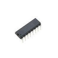
TEA1610PN NXP Semiconductors, TEA1610PN Datasheet - Page 6

TEA1610PN
Manufacturer Part Number
TEA1610PN
Description
AC/DC Switching Converters RESONANT SMPS
Manufacturer
NXP Semiconductors
Datasheet
1.TEA1610PN.pdf
(21 pages)
Specifications of TEA1610PN
Mounting Style
SMD/SMT
Package / Case
SOT-38
Lead Free Status / Rohs Status
Lead free / RoHS Compliant
Other names
TEA1610P/N5,112
NXP Semiconductors
TEA1610T_P_3
Product data sheet
8.2 Oscillator
8.3 Dead time resistor
t
The internal oscillator is a current-controlled oscillator that generates a sawtooth output.
The frequency of the sawtooth is determined by the external capacitor C
flowing into the IFS and IRS pins.
The minimum frequency and the dead time are set by the capacitor C
and R
frequency is exactly twice the bridge frequency to achieve an accurate 50 % duty factor.
An overview of the oscillator and driver signals is given in
The dead time resistor R
current input pin (see
temperature independent value of 0.6 V. The current that flows into the IFS pin is
determined by the value of resistor R
IFS input current equals the discharge current of capacitor C
slope of the oscillator.
The falling slope time is used to create a dead time (t
actions of the half-bridge switches:
I
t
dt
IFS
IFS
Fig 6. Oscillator and driver signals
=
=
=
C
--------------------------
dt
t
. The maximum frequency is set by resistor R
f
2.4V
-----------
dt
R
I
IFS
dt
V
Cf
GH-SH
CF
GL
0
0
Figure
Rev. 03 — 26 March 2007
dt
dead time (high to low)
is connected between the 3 V reference pin (V
10). The voltage on the IFS pin is kept constant at a
Zero-voltage-switching resonant converter controller
dt
and the 2.4 V voltage drop across this resistor. The
TEA1610P; TEA1610T
dt
dead time (low to high)
) between two successive switching
f
(see
Figure
Figure
f
and determines the falling
t
6.
10). The oscillator
f
and resistors R
mgt999
© NXP B.V. 2007. All rights reserved.
f
REF
and the currents
) and the IFS
6 of 21
f(min)


