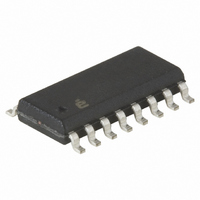
HIN232ECBN Intersil, HIN232ECBN Datasheet - Page 7

HIN232ECBN
Manufacturer Part Number
HIN232ECBN
Description
IC TXRX RS-232 5V ESD 16-SOIC
Manufacturer
Intersil
Type
Transceiverr
Datasheet
1.HIN202ECBNZ-T.pdf
(22 pages)
Specifications of HIN232ECBN
Number Of Drivers/receivers
2/2
Protocol
RS232
Voltage - Supply
4.5 V ~ 5.5 V
Mounting Type
Surface Mount
Package / Case
16-SOIC (3.9mm Width)
Lead Free Status / RoHS Status
Contains lead / RoHS non-compliant
Available stocks
Company
Part Number
Manufacturer
Quantity
Price
Company:
Part Number:
HIN232ECBN
Manufacturer:
HARRIS
Quantity:
11
Company:
Part Number:
HIN232ECBNZ
Manufacturer:
Intersil
Quantity:
1 263
Company:
Part Number:
HIN232ECBNZ
Manufacturer:
NXP
Quantity:
1 000
Company:
Part Number:
HIN232ECBNZ-T
Manufacturer:
INTERSIL
Quantity:
22 140
Part Number:
HIN232ECBNZ-T
Manufacturer:
INTERSIL
Quantity:
20 000
Pinouts
Pin Descriptions
EN, EN
SD, SD
R
T
GND
V
C1+
C2+
PIN
C1-
C2-
R
T
NC
OUT
V+
OUT
V-
CC
IN
IN
HIN232E (PDIP, SOIC, SSOP, TSSOP)
(Continued)
T2
Power Supply Input 5V ±10%, (5V ±5% HIN207E).
Internally generated positive supply (+10V nominal).
Internally generated negative supply (-10V nominal).
Ground Lead. Connect to 0V.
External capacitor (+ terminal) is connected to this lead.
External capacitor (- terminal) is connected to this lead.
External capacitor (+ terminal) is connected to this lead.
External capacitor (- terminal) is connected to this lead.
Transmitter Inputs. These leads accept TTL/CMOS levels. An internal 400kΩ pull-up resistor to V
Transmitter Outputs. These are RS-232 levels (nominally ±10V).
Receiver Inputs. These inputs accept RS-232 input levels. An internal 5kΩ pull-down resistor to GND is connected to each input.
Receiver Outputs. These are TTL/CMOS levels.
Receiver Enable Input. With EN = 5V (HIN213E EN=0V), the receiver outputs are placed in a high impedance state.
Shutdown Input. With SD = 5V (HIN213E SD = 0V), the charge pump is disabled, the receiver outputs are in a high impedance
state (except R4 and R5 of HIN213E) and the transmitters are shut off.
No Connect. No connections are made to these leads.
R2
HIN202E, HIN206E, HIN207E, HIN208E, HIN211E, HIN213E, HIN232E
OUT
C1+
C2+
C1-
C2-
V+
V-
IN
1
2
3
4
5
6
7
8
TOP VIEW
7
16
15
14
13
12
11
10
9
V
GND
T1
R1
R1
T1
T2
R2
CC
OUT
IN
IN
IN
OUT
OUT
FUNCTION
R1
R2
0.1µF
0.1µF
T1
T2
OUT
OUT
IN
IN
+
+
11
10
12
1
3
4
5
9
C1+
C1-
C2+
C2-
+5V
+5V
400kΩ
400kΩ
VOLTAGE INVERTER
VOLTAGE INVERTER
+10V TO -10V
+5V TO 10V
GND
T1
T2
V
R1
R2
CC
16
+5V
15
CC
is connected to each lead.
5kΩ
5kΩ
V+
V-
2
6
14
7
13
8
November 4, 2005
+
+
0.1µF
0.1µF
R1
R2
T1
T2
FN4315.16
OUT
OUT
IN
IN


