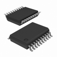
PCA8574ATS,118 NXP Semiconductors, PCA8574ATS,118 Datasheet - Page 7

PCA8574ATS,118
Manufacturer Part Number
PCA8574ATS,118
Description
IC I/O EXPANDER I2C 8B 20SSOP
Manufacturer
NXP Semiconductors
Datasheet
1.PCA8574PW112.pdf
(27 pages)
Specifications of PCA8574ATS,118
Package / Case
20-SSOP
Interface
I²C
Number Of I /o
8
Interrupt Output
Yes
Frequency - Clock
400kHz
Voltage - Supply
2.3 V ~ 5.5 V
Operating Temperature
-40°C ~ 85°C
Mounting Type
Surface Mount
Includes
POR
Logic Family
PCA8574
Number Of Lines (input / Output)
8.0 / 8.0
Operating Supply Voltage
2.3 V to 5.5 V
Power Dissipation
400 mW
Operating Temperature Range
- 40 C to + 85 C
Input Voltage
5.5 V
Logic Type
I/O Expander
Maximum Clock Frequency
400 KHz
Mounting Style
SMD/SMT
Number Of Input Lines
8.0
Number Of Output Lines
8.0
Output Current
50 mA
Output Voltage
5.5 V
Lead Free Status / RoHS Status
Lead free / RoHS Compliant
Lead Free Status / RoHS Status
Lead free / RoHS Compliant, Lead free / RoHS Compliant
Other names
935283491118
PCA8574ATS-T
PCA8574ATS-T
PCA8574ATS-T
PCA8574ATS-T
NXP Semiconductors
8. I/O programming
PCA8574_PCA8574A_2
Product data sheet
8.1 Quasi-bidirectional I/O architecture
8.2 Writing to the port (Output mode)
Table 5.
The PCA8574/74A’s 8 ports (see
either as input or output ports. Input data is transferred from the ports to the
microcontroller in the Read mode (see
the Write mode (see
This quasi-bidirectional I/O can be used as an input or output without the use of a control
signal for data directions. At power-on the I/Os are HIGH. In this mode only a current
source (I
edges into heavily loaded outputs. These devices turn on when an output is written HIGH,
and are switched off by the negative edge of SCL. The I/Os should be HIGH before being
used as inputs. After power-on, as all the I/Os are set HIGH, all of them can be used as
inputs. Any change in setting of the I/Os as either inputs or outputs can be done with the
write mode.
Remark: If a HIGH is applied to an I/O which has been written earlier to LOW, a large
current (I
To write, the master (microcontroller) first addresses the slave device. By setting the last
bit of the byte containing the slave address to logic 0 the write mode is entered. The
PCA8574/74A acknowledges and the master sends the data byte for P7 to P0 and is
acknowledged by the PCA8574/74A. The 8-bit data is presented on the port lines after it
has been acknowledged by the PCA8574/74A.
The number of data bytes that can be sent successively is not limited. The previous data
is overwritten every time a data byte has been sent.
A6
0
0
0
0
0
0
0
0
A5
1
1
1
1
1
1
1
1
OH
OL
PCA8574A address map
) to V
) will flow to V
A4
1
1
1
1
1
1
1
1
DD
is active. An additional strong pull-up to V
Figure
Rev. 02 — 14 May 2007
A3
1
1
1
1
1
1
1
1
SS
.
8).
A2
0
0
0
0
1
1
1
1
Figure
Remote 8-bit I/O expander for I
Figure
2) are entirely independent and can be used
A1
0
0
1
1
0
0
1
1
9). Output data is transmitted to the ports in
A0
0
1
0
1
0
1
0
1
Address
38h
39h
3Ah
3Bh
3Ch
3Dh
3Eh
3Fh
PCA8574/74A
DD
(I
trt(pu)
2
C-bus with interrupt
) allows fast rising
© NXP B.V. 2007. All rights reserved.
7 of 27


