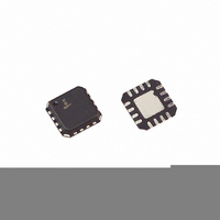
ISL43145IRZ-T Intersil, ISL43145IRZ-T Datasheet - Page 8

ISL43145IRZ-T
Manufacturer Part Number
ISL43145IRZ-T
Description
IC SWITCH QUAD SPST 16QFN
Manufacturer
Intersil
Datasheet
1.ISL43144IR.pdf
(15 pages)
Specifications of ISL43145IRZ-T
Function
Switch
Circuit
4 x SPST - NC/NO
On-state Resistance
25 Ohm
Voltage Supply Source
Single, Dual Supply
Voltage - Supply, Single/dual (±)
±2 V ~ 6 V, 2 V ~ 12 V
Current - Supply
0.01µA
Operating Temperature
-40°C ~ 85°C
Mounting Type
Surface Mount
Package / Case
16-VQFN Exposed Pad, 16-HVQFN, 16-SQFN, 16-DHVQFN
Lead Free Status / RoHS Status
Lead free / RoHS Compliant
Electrical Specifications: 12V Supply
Test Circuits and Waveforms
Logic input waveform is inverted for switches that have the opposite
logic sense.
Logic input waveform is inverted for switches that have the opposite
logic sense.
POWER SUPPLY CHARACTERISTICS
Positive Supply Current, I+
Negative Supply Current, I-
OUTPUT
SWITCH
SWITCH
LOGIC
INPUT
INPUT
OUTPUT
SWITCH
LOGIC
INPUT
V
OUT
PARAMETER
V
FIGURE 1A. MEASUREMENT POINTS
FIGURE 2A. MEASUREMENT POINTS
NX
3V
0V
0V
Q = ∆V
ON
OUT
∆V
x C
t
ON
OUT
50%
L
8
OFF
90%
V+ = 13V, V
t
OFF
V
OUT
ISL43143, ISL43144, ISL43145
ON
IN
= 0V or V+, Switch On or Off
TEST CONDITIONS
FIGURE 2. CHARGE INJECTION
Test Conditions: V+ = +10.8V to +13.2V, V- = GND = 0V, V
(Note 5), Unless Otherwise Specified (Continued)
t
t
90%
FIGURE 1. SWITCHING TIMES
r
f
< 20ns
< 20ns
3V
0V
Repeat test for all switches. C
capacitance.
Repeat test for all switches. C
capacitance.
V
V
NX
G
C
SWITCH
R
INPUT
G
LOGIC
V
INPUT
TEMP
OUT
C
(°C)
Full
Full
25
25
FIGURE 1B. TEST CIRCUIT
FIGURE 2B. TEST CIRCUIT
IN
NO or NC
COM
=
V-
V (NO or NC)
V+
(NOTE 6)
GND
GND
MIN
L
L
-1
-1
-1
-1
V+
includes fixture and stray
includes fixture and stray
C
NO or NC
V-
INH
IN
C
LOGIC
INPUT
COM
------------------------------
R
0.01
TYP
0.01
C
= 3.0V, V
L
-
-
+
R
R
L
(
ON
(NOTE 6) UNITS
INL
)
300Ω
MAX
R
L
December 1, 2005
1
1
1
1
V
= 0.8V
OUT
C
L
FN6037.3
35pF
V
C
OUT
L
µA
µA
µA
µA


