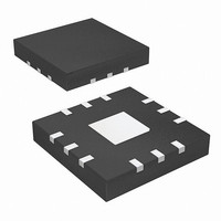
ISL54217IRTZ Intersil, ISL54217IRTZ Datasheet - Page 7

ISL54217IRTZ
Manufacturer Part Number
ISL54217IRTZ
Description
IC USB SWITCH DUAL SP3T 12TQFN
Manufacturer
Intersil
Datasheet
1.ISL54217IRTZ.pdf
(24 pages)
Specifications of ISL54217IRTZ
Function
USB Switch
Circuit
2 x SP3T
On-state Resistance
8 Ohm
Voltage Supply Source
Single Supply
Voltage - Supply, Single/dual (±)
2.7 V ~ 4.6 V
Operating Temperature
-40°C ~ 85°C
Mounting Type
Surface Mount
Package / Case
12-TQFN
Lead Free Status / RoHS Status
Lead free / RoHS Compliant
Electrical Specifications - 2.7V to 3.6V Supply
NOTES:
11. V
12. The algebraic convention, whereby the most negative value is a minimum and the most positive a maximum, is used in this
13. Parameters with MIN and/or MAX limits are 100% tested at +25°C, unless otherwise specified. Temperature limits established
14. Flatness is defined as the difference between maximum and minimum value of on-resistance over the specified analog signal
15. Limits established by characterization and are not production tested.
16. r
Test Circuits and Waveforms
Logic input waveform is inverted for switches that have the
opposite logic sense.
C0, C1 Pull-Down Resistor, R
FIGURE 1A. ADDRESS t
data sheet.
by characterization and are not production tested.
range.
with lowest max r
OUTPUT
SWITCH
SWITCH
ON
LOGIC
LOGIC
INPUT
INPUT
matching between channels is calculated by subtracting the channel with the highest max r
PARAMETER
V
V
C0,C1
C0,C1
V
= Input voltage to perform proper function.
INPUT
0V
ON
value, between L and R or between 1D+ and 1D- or between 2D+ and 2D-.
t
TRANS
ON
50%
Cx
7
90%
MEASUREMENT POINTS
V
or C1 pin and calculate resistance value.
t
DD
OFF
V
OUT
= 3.6V, C0 = C1= 3.6V, Measure current into C0
FIGURE 1. SWITCHING TIMES
t
t
TEST CONDITIONS
90%
r
f
< 20ns
< 20ns
Test Conditions: V
V
Boldface limits apply over the operating temperature range,
-40°C to +85°C. (Continued)
ISL54217
C1L
= 0.5V, (Note 11), Unless Otherwise Specified.
Repeat test for all switches. C
capacitance.
SWITCH
LOGIC
INPUT
INPUT
FIGURE 1B. ADDRESS t
DD
= +3.0V, GND = 0V, V
V
INPUT
V
C0, C1
OUT
TEMP
(°C)
=
Full
V
V (INPUT)
DD
GND
12, 13) TYP
(Notes
L
MIN
includes fixture and stray
TRANS
C0H
-
ON
C
COMx
----------------------- -
R
, V
value from the channel
L
R
+
C1H
L
TEST CIRCUIT
r
4
ON
= 1.4V, V
12, 13) UNITS
(Notes
R
50Ω
MAX
L
V
-
OUT
June 17, 2010
C0L
10pF
C
FN6817.4
L
MΩ
,


