M50FW040K1 STMicroelectronics, M50FW040K1 Datasheet - Page 14
M50FW040K1
Manufacturer Part Number
M50FW040K1
Description
Flash 3.6V 4M (512Kx8)
Manufacturer
STMicroelectronics
Datasheet
1.M50FW040K1.pdf
(41 pages)
Specifications of M50FW040K1
Data Bus Width
8 bit
Memory Type
NOR
Memory Size
4 Mbit
Architecture
Sectored
Interface Type
Firmware Hub
Access Time
11 ns, 50 ns
Supply Voltage (max)
3.6 V
Supply Voltage (min)
3 V
Maximum Operating Current
20 mA
Operating Temperature
+ 70 C
Mounting Style
SMD/SMT
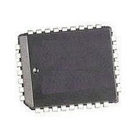
Package / Case
PLCC-32
Organization
512 KB x 8
Lead Free Status / Rohs Status
No
Available stocks
Company
Part Number
Manufacturer
Quantity
Price
Company:

Part Number:
M50FW040K1
Manufacturer:
ST
Quantity:
3 112
Company:
Part Number:
M50FW040K1
Manufacturer:
STM
Quantity:
245
Company:
Part Number:
M50FW040K1
Manufacturer:
QP-SEMI
Quantity:
13
Part Number:
M50FW040K1
Manufacturer:
ST
Quantity:
20 000
Company:
Part Number:
M50FW040K1T
Manufacturer:
TI
Quantity:
125
Part Number:
M50FW040K1T
Manufacturer:
ST
Quantity:
20 000


M50FW040
COMMAND INTERFACE
All Bus Write operations to the memory are inter-
preted by the Command Interface. Commands
consist of one or more sequential Bus Write oper-
ations.
After power-up or a Reset operation the memory
enters Read mode.
The commands
7.,
with the text descriptions below.
Read Memory Array Command. The Read Mem-
ory Array command returns the memory to its
Read mode where it behaves like a ROM or
EPROM. One Bus Write cycle is required to issue
the Read Memory Array command and return the
memory to Read mode. Once the command is is-
sued the memory remains in Read mode until an-
other command is issued. From Read mode Bus
Read operations will access the memory array.
While the Program/Erase Controller is executing a
Program or Erase operation the memory will not
accept the Read Memory Array command until the
operation completes.
Read Status Register Command. The Read Sta-
tus Register command is used to read the Status
Register. One Bus Write cycle is required to issue
the Read Status Register command. Once the
command is issued subsequent Bus Read opera-
tions read the Status Register until another com-
mand is issued. See the section on the Status
Register for details on the definitions of the Status
Register bits.
Read Electronic Signature Command. The Read
Electronic Signature command is used to read the
Manufacturer Code and the Device Code. One
Bus Write cycle is required to issue the Read Elec-
tronic Signature command. Once the command is
issued subsequent Bus Read operations read the
Manufacturer Code or the Device Code until an-
other command is issued.
After the Read Electronic Signature Command is
issued the Manufacturer Code and Device Code
can be read using Bus Read operations using the
addresses in
Program Command. The Program command
can be used to program a value to one address in
the memory array at a time. Two Bus Write opera-
tions are required to issue the command; the sec-
ond Bus Write cycle latches the address and data
in the internal state machine and starts the Pro-
gram/Erase Controller. Once the command is is-
sued subsequent Bus Read operations read the
Status Register. See the section on the Status
Register for details on the definitions of the Status
Register bits.
14/41
Commands. Refer to
Table 6.
are summarized in
Table 7.
in conjunction
Table
If the address falls in a protected block then the
Program operation will abort, the data in the mem-
ory array will not be changed and the Status Reg-
ister will output the error.
During the Program operation the memory will
only accept the Read Status Register command
and the Program/Erase Suspend command. All
other commands will be ignored. Typical Program
times are given in
Note that the Program command cannot change a
bit set at ‘0’ back to ‘1’ and attempting to do so will
not cause any modification on its value. The Erase
command must be used to set all of the bits in the
block to ‘1’.
See
Code, for a suggested flowchart on using the Pro-
gram command.
Erase Command. The Erase command can be
used to erase a block. Two Bus Write operations
are required to issue the command; the second
Bus Write cycle latches the block address in the in-
ternal state machine and starts the Program/Erase
Controller. Once the command is issued subse-
quent Bus Read operations read the Status Reg-
ister. See the section on the Status Register for
details on the definitions of the Status Register
bits.
If the block is protected then the Erase operation
will abort, the data in the block will not be changed
and the Status Register will output the error.
During the Erase operation the memory will only
accept the Read Status Register command and
the Program/Erase Suspend command. All other
commands will be ignored. Typical Erase times
are given in
The Erase command sets all of the bits in the block
to ‘1’. All previous data in the block is lost.
See
Code, for a suggested flowchart on using the
Erase command.
Clear Status Register Command. The Clear Sta-
tus Register command can be used to reset bits 1,
3, 4 and 5 in the Status Register to ‘0’. One Bus
Write is required to issue the Clear Status Register
command. Once the command is issued the mem-
ory returns to its previous mode, subsequent Bus
Read operations continue to output the same data.
The bits in the Status Register are sticky and do
not automatically return to ‘0’ when a new Program
or Erase command is issued. If an error occurs
then it is essential to clear any error bits in the Sta-
tus Register by issuing the Clear Status Register
command before attempting a new Program or
Erase command.
Figure 19., Program Flowchart and Pseudo
Figure 21., Erase Flowchart and Pseudo
Table 12.
Table 12.
Related parts for M50FW040K1
Image
Part Number
Description
Manufacturer
Datasheet
Request
R

Part Number:
Description:
Fast Recovery High Voltage Silicon Diodes
Manufacturer:
Voltage Multipliers, Inc.

Part Number:
Description:
STMicroelectronics [RIPPLE-CARRY BINARY COUNTER/DIVIDERS]
Manufacturer:
STMicroelectronics
Datasheet:
Part Number:
Description:
STMicroelectronics [LIQUID-CRYSTAL DISPLAY DRIVERS]
Manufacturer:
STMicroelectronics
Datasheet:

Part Number:
Description:
BOARD EVAL FOR MEMS SENSORS
Manufacturer:
STMicroelectronics
Datasheet:
Part Number:
Description:
NPN TRANSISTOR POWER MODULE
Manufacturer:
STMicroelectronics
Datasheet:
Part Number:
Description:
TURBOSWITCH ULTRA-FAST HIGH VOLTAGE DIODE
Manufacturer:
STMicroelectronics
Datasheet:
Part Number:
Description:
Manufacturer:
STMicroelectronics
Datasheet:
Part Number:
Description:
DIODE / SCR MODULE
Manufacturer:
STMicroelectronics
Datasheet:
Part Number:
Description:
DIODE / SCR MODULE
Manufacturer:
STMicroelectronics
Datasheet:
Part Number:
Description:
Search -----> STE16N100
Manufacturer:
STMicroelectronics
Datasheet:
Part Number:
Description:
Search ---> STE53NA50
Manufacturer:
STMicroelectronics
Datasheet:
Part Number:
Description:
NPN Transistor Power Module
Manufacturer:
STMicroelectronics
Datasheet: