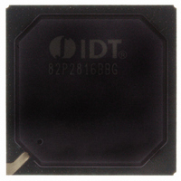
IDT82P2816BBG IDT, Integrated Device Technology Inc, IDT82P2816BBG Datasheet - Page 31

IDT82P2816BBG
Manufacturer Part Number
IDT82P2816BBG
Description
IC LINE INTERFACE UNIT 416-PBGA
Manufacturer
IDT, Integrated Device Technology Inc
Datasheet
1.IDT82P2816BBG.pdf
(146 pages)
Specifications of IDT82P2816BBG
Function
Line Interface Unit (LIU)
Interface
E1, J1, T1
Number Of Circuits
1
Voltage - Supply
1.8V, 3.3V
Operating Temperature
-40°C ~ 85°C
Mounting Type
Surface Mount
Package / Case
*
Includes
Defect and Alarm Detection, Driver Over-Current Detection and Protection, LLOS Detection, PRBSARB / IB Detection and Generation
Number Of Transceivers
1
Screening Level
Industrial
Mounting
Surface Mount
Operating Temperature (min)
-40C
Operating Temperature (max)
85C
Lead Free Status / RoHS Status
Lead free / RoHS Compliant
Current - Supply
-
Power (watts)
-
Lead Free Status / RoHS Status
Compliant, Lead free / RoHS Compliant
Other names
800-1702
82P2816BBG
82P2816BBG
Available stocks
Company
Part Number
Manufacturer
Quantity
Price
Company:
Part Number:
IDT82P2816BBG
Manufacturer:
IDT Integrated Device Technolo
Quantity:
135
Company:
Part Number:
IDT82P2816BBG
Manufacturer:
IDT
Quantity:
70
Company:
Part Number:
IDT82P2816BBG
Manufacturer:
IDT, Integrated Device Technology Inc
Quantity:
10 000
Table-5 PULS[3:0] Setting in T1/J1 Mode
Figure-13. It is measured in the near end line side, as shown in Figure-
14.
signals (output from TTIP and TRING) are coupled to a 75 Ω coaxial
cable using Internal Impedance matching mode; the PULS[3:0] should
be set to ‘0001’ for other E1 interfaces. Refer to Table-6 for details.
Functional Description
IDT82P2816
In E1 applications, the waveform template meets G.703, as shown in
In E1 applications, the PULS[3:0] should be set to ‘0000’ if differential
-0.20
0.80
0.00
1.00
0.60
0.40
0.20
1.20
-0.6
DSX1 - 133 ~ 266 ft
DSX1 - 266 ~ 399 ft
DSX1 - 399 ~ 533 ft
DSX1 - 533 ~ 655 ft
Cable Conditions
DSX1 - 0 ~ 133 ft
Figure-13 E1 Waveform Template
J1 - 0 ~ 655 ft
-0.4
-0.2
Time in Unit Intervals
0
0.2
PULS[3:0]
0010
0011
0100
0101
0110
0111
0.4
0.6
16(+1) CHANNEL HIGH-DENSITY T1/E1/J1 LINE INTERFACE UNIT
31
Figure-14 E1 Waveform Template Measurement Circuit
waveform amplitude can be adjusted to get the desired waveform.
SCAL,...) is ‘110110’ which is also the default value. The adjusting is
made by increasing or decreasing by ‘1’ from the standard value to scale
up or down at a percentage ratio of 2% against the preset waveform
amplitude.
‘100001’ to get the standard amplitude. The adjusting is made by
increasing or decreasing by ‘1’ from the standard value to scale up or
down at a percentage ratio of 3%.
be got based on the preset waveform template:
Table-6 PULS[3:0] Setting in E1 Mode
Internal Impedance matching mode
After one of the preset waveform templates is selected, the preset
In T1 mode, the standard value of the SCAL[5:0] bits (b5~0,
In E1 mode, the SCAL[5:0] bits (b5~0, SCAL,...) should be set to
In summary, do the following step by step, the desired waveform will
• Select one preset waveform template by setting the PULS[3:0] bits
• Write ‘100001 to the SCAL[5:0] bits (b5~0, SCAL,...) if E1 mode is
• Write the scaling value to the SCAL[5:0] bits (b5~0, SCAL,...) to
Note: R
(b3~0, PULS,...);
selected.
scale the amplitude of the selected preset waveform template (-
this step is optional).
E1 75 Ω
IDT82P2816
Interface Conditions
Other E1 interface
LOAD
differential interface,
= 75 Ω or 120 Ω (+ 5%)
TRINGn
TTIPn
February 6, 2009
PULS[3:0]
R
0000
0001
LOAD
V
OUT


