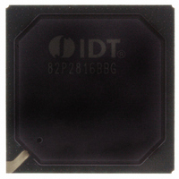
IDT82P2816BBG IDT, Integrated Device Technology Inc, IDT82P2816BBG Datasheet - Page 65

IDT82P2816BBG
Manufacturer Part Number
IDT82P2816BBG
Description
IC LINE INTERFACE UNIT 416-PBGA
Manufacturer
IDT, Integrated Device Technology Inc
Datasheet
1.IDT82P2816BBG.pdf
(146 pages)
Specifications of IDT82P2816BBG
Function
Line Interface Unit (LIU)
Interface
E1, J1, T1
Number Of Circuits
1
Voltage - Supply
1.8V, 3.3V
Operating Temperature
-40°C ~ 85°C
Mounting Type
Surface Mount
Package / Case
*
Includes
Defect and Alarm Detection, Driver Over-Current Detection and Protection, LLOS Detection, PRBSARB / IB Detection and Generation
Number Of Transceivers
1
Screening Level
Industrial
Mounting
Surface Mount
Operating Temperature (min)
-40C
Operating Temperature (max)
85C
Lead Free Status / RoHS Status
Lead free / RoHS Compliant
Current - Supply
-
Power (watts)
-
Lead Free Status / RoHS Status
Compliant, Lead free / RoHS Compliant
Other names
800-1702
82P2816BBG
82P2816BBG
Available stocks
Company
Part Number
Manufacturer
Quantity
Price
Company:
Part Number:
IDT82P2816BBG
Manufacturer:
IDT Integrated Device Technolo
Quantity:
135
Company:
Part Number:
IDT82P2816BBG
Manufacturer:
IDT
Quantity:
70
Company:
Part Number:
IDT82P2816BBG
Manufacturer:
IDT, Integrated Device Technology Inc
Quantity:
10 000
Table-27 Microprocessor Interface
4.1.1
(1.8V and 3.3V) reach approximately 60% of the standard value of VDD,
power-on reset begins. If MCLK is applied, power-on reset will complete
within 1 ms maximum; if MCLK is not applied, the device remains in
reset state.
4.1.2
should be more than 1 µs. If the RST pin is held low continuously, the
device remains in reset state.
4.1.3
ated, global software reset completes in 1 µs maximum.
4.1.4
software reset. Once initiated, per-channel software reset completes in 1
µs maximum and the CHRST bit (b1, CHCF,...) is self cleared.
Miscellaneous
IDT82P2816
Power-on reset is initiated during power-up. When all VDD inputs
Pulling the RST pin to low will initiate hardware reset. The reset cycle
Writing the RST register will initiate global software reset. Once initi-
Writing a ‘1’ to the CHRST bit (b1, CHCF,...) will initiate per-channel
VDDIO
GNDD
P/S
POWER-ON RESET
HARDWARE RESET
GLOBAL SOFTWARE RESET
PER-CHANNEL SOFTWARE RESET
INT/MOT
GNDD
Open
Open
GNDD
GNDD
GNDD
Open
Open
IM
Parallel Motorola Non-Multiplexed microprocessor interface
Parallel Intel Non-Multiplexed microprocessor interface
Parallel Motorola Multiplexed microprocessor interface
Parallel Intel Multiplexed microprocessor interface
Serial microprocessor interface
Microprocessor Interface
16(+1) CHANNEL HIGH-DENSITY T1/E1/J1 LINE INTERFACE UNIT
65
4.2
registers in the device. The interface consists of:
IM pins, as shown in Table-27. The interfaced pins in different interfaces
are also listed in Table-27. Refer to Section 8.13 Microprocessor Inter-
face Timing for the timing characteristics.
This reset is different from other resets, for:
• It does not reset the T1E1 bit (b0, CHCF,...). That is, the operation
• It does not reset the global registers, state machines and common
• It does not reset the other channels.
The microprocessor interface provides access to read and write the
• Serial microprocessor interface;
• Parallel Motorola Non-Multiplexed microprocessor interface;
• Parallel Motorola Multiplexed microprocessor interface;
• Parallel Intel Non-Multiplexed microprocessor interface;
• Parallel Intel Multiplexed microprocessor interface.
The microprocessor interface is selected by the P/ S , INT/ MOT and
mode of each channel is not changed;
pins (including the pins of clock generator, microprocessor inter-
face and JTAG interface);
MICROPROCESSOR INTERFACE
CS , ALE, RD , WR , RDY, D[7:0], A[10:8]
CS , AS, DS , R/ W , ACK , D[7:0], A[10:8]
CS , DS , R/ W , ACK , D[7:0], A[10:0]
CS , RD , WR , RDY, D[7:0], A[10:0]
CS , SCLK, SDI, SDO
Interfaced Pins
February 6, 2009


