LM4781TA/NOPB National Semiconductor, LM4781TA/NOPB Datasheet - Page 19
LM4781TA/NOPB
Manufacturer Part Number
LM4781TA/NOPB
Description
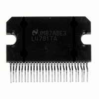
IC AMP AUDIO PWR 35W AB TO220-27
Manufacturer
National Semiconductor
Series
Overture™r
Type
Class ABr
Datasheet
1.LM4781TANOPB.pdf
(25 pages)
Specifications of LM4781TA/NOPB
Output Type
3-Channel
Max Output Power X Channels @ Load
35W x 3 @ 8 Ohm
Voltage - Supply
20 V ~ 70 V, ±10 V ~ 35 V
Features
Depop, Mute, Short-Circuit and Thermal Protection
Mounting Type
Through Hole
Package / Case
TO-220-27 (Bent and Staggered Leads)
For Use With
LM4781TABD - BOARD EVALUATION LM4781TA
Lead Free Status / RoHS Status
Lead free / RoHS Compliant
Other names
*LM4781TA
*LM4781TA/NOPB
LM4781TA
*LM4781TA/NOPB
LM4781TA
Available stocks
Company
Part Number
Manufacturer
Quantity
Price
Company:

Part Number:
LM4781TA/NOPB
Manufacturer:
National Semiconductor
Quantity:
135


Application Information
Note 19: CCIR/ARM: A Practical Noise Measurement Method; by Ray
Dolby, David Robinson and Kenneth Gundry, AES Preprint No. 1353 (F-3).
In addition to noise filtering, differing meter types give differ-
ent noise readings. Meter responses include:
1. RMS reading,
2. average responding,
3. peak reading, and
4. quasi peak reading.
Although theoretical noise analysis is derived using true
RMS based calculations, most actual measurements are
taken with ARM (Average Responding Meter) test equip-
ment.
Typical signal-to-noise figures are listed for an A-weighted
filter which is commonly used in the measurement of noise.
The shape of all weighting filters is similar, with the peak of
the curve usually occurring in the 3kHz–7kHz region.
LEAD INDUCTANCE
Power op amps are sensitive to inductance in the output
leads, particularly with heavy capacitive loading. Feedback
to the input should be taken directly from the output terminal,
minimizing common inductance with the load.
Lead inductance can also cause voltage surges on the sup-
plies. With long leads to the power supply, energy is stored in
the lead inductance when the output is shorted. This energy
can be dumped back into the supply bypass capacitors when
the short is removed. The magnitude of this transient is
reduced by increasing the size of the bypass capacitor near
the IC. With at least a 20µF local bypass, these voltage
(Continued)
19
surges are important only if the lead length exceeds a couple
feet (
and ground leads minimizes the effect.
PHYSICAL IC MOUNTING CONSIDERATIONS
Mounting of the package to a heat sink must be done such
that there is sufficient pressure from the mounting screws to
insure good contact with the heat sink for efficient heat flow.
Over tightening the mounting screws will cause the package
to warp reducing contact area with the heat sink. Less
contact with the heat sink will increase the thermal resis-
tance from the package case to the heat sink (θ
in higher operating die temperatures and possible unwanted
thermal shut down activation. Extreme over tightening of the
mounting screws will cause severe physical stress resulting
in cracked die and catastrophic IC failure. The recom-
mended mounting screw size is M3 with a maximum torque
of 50 N-cm. Additionally, it is best to use washers under the
screws to distribute the force over a wider area or a screw
with a wide flat head. To further distribute the mounting force
a solid mounting bar in front of the package and secured in
place with the two mounting screws may be used. Other
mounting options include a spring clip. If the package is
secured with pressure on the front of the package the maxi-
mum pressure on the molded plastic should not exceed
150N/mm
Additionally, if the mounting screws are used to force the
package into correct alignment with the heat sink, package
stress will be increased. This increase in package stress will
result in reduced contact area with the heat sink increasing
die operating temperature and possible catastrophic IC fail-
ure.
>
1µH lead inductance). Twisting together the supply
2
.
CS
www.national.com
) resulting
Related parts for LM4781TA/NOPB
Image
Part Number
Description
Manufacturer
Datasheet
Request
R

Part Number:
Description:
Audio Power Amplifier IC
Manufacturer:
National Semiconductor
Datasheet:

Part Number:
Description:
National Semiconductor [8-Bit D/A Converter]
Manufacturer:
National Semiconductor
Datasheet:
Part Number:
Description:
National Semiconductor [Media Coprocessor]
Manufacturer:
National Semiconductor
Datasheet:
Part Number:
Description:
Digitally Controlled Tone and Volume Circuit with Stereo Audio Power Amplifier, Microphone Preamp Stage and National 3D Sound
Manufacturer:
National Semiconductor
Datasheet:
Part Number:
Description:
Digitally Controlled Tone and Volume Circuit with Stereo Audio Power Amplifier, Microphone Preamp Stage and National 3D Sound
Manufacturer:
National Semiconductor
Datasheet:
Part Number:
Description:
AC97 Rev 2 Codec with Sample Rate Conversion and National 3D Sound
Manufacturer:
National Semiconductor
Part Number:
Description:
Manufacturer:
National Semiconductor
Datasheet:
Part Number:
Description:
Manufacturer:
National Semiconductor
Datasheet:
Part Number:
Description:
General Purpose, Low Voltage, Low Power, Rail-to-Rail Output Operational Amplifiers
Manufacturer:
National Semiconductor
Datasheet:
Part Number:
Description:
8-bit 20 MSPS flash A/D converter.
Manufacturer:
National Semiconductor
Datasheet:
Part Number:
Description:
Low Noise Quad Operational Amplifier
Manufacturer:
National Semiconductor
Datasheet:
Part Number:
Description:
Quad Differential Line Receivers
Manufacturer:
National Semiconductor
Datasheet:
Part Number:
Description:
Quad High Speed Trapezoidal? Bus Transceiver
Manufacturer:
National Semiconductor
Datasheet:
Part Number:
Description:
Dual Line Receiver
Manufacturer:
National Semiconductor
Datasheet: