TFA9841J/N1,112 NXP Semiconductors, TFA9841J/N1,112 Datasheet
TFA9841J/N1,112
Specifications of TFA9841J/N1,112
935274366112
TFA9841J


Related parts for TFA9841J/N1,112


TFA9841J/N1,112 Summary of contents
Page 1
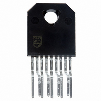
General description The TFA9841J contains one audio power amplifier. The TFA9841J can be used as one Single-Ended (SE) channel with a fixed gain of 26 dB. The TFA9841J comes in a 9-pin DIL-bent-SIL (DBS9P) power package. The TFA9841J is ...
Page 2
Philips Semiconductors 4. Quick reference data Table 1: Symbol Parameter stb P o THD G v SVRR 5. Ordering information Table 2: Type number TFA9841J DBS9P 6. Block diagram Fig 1. Block diagram. 9397 750 ...
Page 3
Philips Semiconductors 7. Pinning information 7.1 Pinning Fig 2. Pin configuration. 7.2 Pin description Table 3: Symbol IN1 OUT1 CIV n.c. GND SVR MODE n. TAB 8. Functional description 8.1 Input configuration The input cut-off frequency is: f ...
Page 4
Philips Semiconductors As shown in the switch-on delay during charging of the input capacitors can be minimized. This results in a good low frequency response and good switch-on behavior. 8.2 Power amplifier The power amplifi Single-Ended (SE) amplifier ...
Page 5
Philips Semiconductors Standby — The current consumption is very low and the output is floating. The device is in standby mode when V Mute — The amplifier is DC-biased but not operational (no audio output). This allows the input coupling ...
Page 6
Philips Semiconductors 9. Limiting values Table 6: Limiting values In accordance with the Absolute Maximum Rating System (IEC 60134). Symbol Parameter V supply voltage CC V input voltage I I repetitive peak output current ORM T storage temperature stg T ...
Page 7
Philips Semiconductors 12. Dynamic characteristics Table 9: Dynamic characteristics kHz amb L Symbol Parameter P output power o THD total harmonic distortion P ...
Page 8
Philips Semiconductors ( THD = kHz. L Fig 5. Output power as function of supply voltage THD N ...
Page 9
Philips Semiconductors ( Fig 9. Total power dissipation as function of channel output power. 9397 750 12014 Preliminary data ...
Page 10
Philips Semiconductors 13. Application information 100 270 7.5 V BC547 2.2 F micro- BC547 controller 1.5 k Fig 11. Typical SE application diagram. Remark: Because of switching inductive loads, the output voltage can ...
Page 11
Philips Semiconductors Fig 12. Printed-circuit board layout (single-sided); components view. 13.1.2 Power supply decoupling Proper supply bypassing is critical for low-noise performance and high supply voltage ripple rejection. The respective capacitor location should be as close as possible to the ...
Page 12
Philips Semiconductors At V see For T 150 This calculation is for an application at worst-case sine-wave output signals. In practice music signals will be applied, which decreases the maximum power dissipation to approximately half of the ...
Page 13
Philips Semiconductors 15. Package outline DBS9P: plastic DIL-bent-SIL power package; 9 leads (lead length 12/11 mm); exposed die pad DIMENSIONS (mm are the original dimensions) (2) (1) (2) UNIT ...
Page 14
Philips Semiconductors 16. Soldering 16.1 Introduction to soldering through-hole mount packages This text gives a brief insight to wave, dip and manual soldering. A more in-depth account of soldering ICs can be found in our Data Handbook IC26; Integrated Circuit ...
Page 15
Philips Semiconductors 17. Revision history Table 11: Revision history Rev Date CPCN Description 01 20040206 - Preliminary data (9397 750 12014) 9397 750 12014 Preliminary data Rev. 01 — 06 February 2004 TFA9841J 1-channel audio amplifi SE) © ...
Page 16
Philips Semiconductors 18. Data sheet status [1] Level Data sheet status Product status I Objective data Development II Preliminary data Qualification III Product data Production [1] Please consult the most recently issued data sheet before initiating or completing a design. ...
Page 17
Philips Semiconductors Contents 1 General description . . . . . . . . . . . . . . . . . . . . . . 1 2 Features . . . . . . . . . ...