LM3875T National Semiconductor, LM3875T Datasheet - Page 14
LM3875T
Manufacturer Part Number
LM3875T
Description
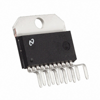
IC AMP AUDIO PWR 56W AB TO220-11
Manufacturer
National Semiconductor
Series
Overture™r
Type
Class ABr
Datasheet
1.LM3875TFNOPB.pdf
(20 pages)
Specifications of LM3875T
Output Type
1-Channel (Mono)
Max Output Power X Channels @ Load
56W x 1 @ 8 Ohm
Voltage - Supply
20 V ~ 84 V, ±10 V ~ 42 V
Features
Short-Circuit and Thermal Protection
Mounting Type
Through Hole
Package / Case
TO-220-11 (Bent and Staggered Leads)
Lead Free Status / RoHS Status
Lead free / RoHS Compliant
Other names
*LM3875T
*LM3875T/NOPB
LM3875T/NOPB
*LM3875T/NOPB
LM3875T/NOPB
Available stocks
Company
Part Number
Manufacturer
Quantity
Price

Part Number:
LM3875T
Manufacturer:
NS/国半
Quantity:
20 000
Company:
Part Number:
LM3875TF/NOPB
Manufacturer:
ABB
Quantity:
12


www.national.com
Application Information
But since we know P
and we are looking for θ
Again it must be noted that the value of θ
upon the system designer’s amplifier application and its
corresponding parameters as described previously. If the
ambient temperature that the audio amplifier is to be working
under is higher than the normal 25˚C, then the thermal
resistance for the heat sink, given all other things are equal,
will need to be smaller.
Equations (1), (4) are the only equations needed in the
determination of the maximum heat sink thermal resistance.
This is, of course, given that the system designer knows the
required supply voltages to drive his rated load at a particular
power output level and the parameters provided by the
semiconductor manufacturer. These parameters are the
junction to case thermal resistance, θ
the recommended Thermalloy Thermacote thermal com-
pound resistance, θ
SIGNAL-TO-NOISE RATIO
In the measurement of the signal-to-noise ratio, misinterpre-
tations of the numbers actually measured are common. One
amplifier may sound much quieter than another, but due to
improper testing techniques, they appear equal in measure-
ments. This is often the case when comparing integrated
circuit designs to discrete amplifier designs. Discrete transis-
tor amps often “run out of gain” at high frequencies and
therefore have small bandwidths to noise as indicated below.
Integrated circuits have additional open loop gain allowing
additional feedback loop gain in order to lower harmonic
distortion and improve frequency response. It is this addi-
tional bandwidth that can lead to erroneous signal-to-noise
measurements if not considered during the measurement
process. In the typical example above, the difference in
bandwidth appears small on a log scale but the factor of 10
in bandwidth, (200 kHz to 2 MHz) can result in a 10 dB
theoretical difference in the signal-to-noise ratio (white noise
is proportional to the square root of the bandwidth in a
system).
In comparing audio amplifiers it is necessary to measure the
magnitude of noise in the audible bandwidth by using a
“weighting” filter (Note 11). A “weighting” filter alters the
frequency response in order to compensate for the average
human ear’s sensitivity to the frequency spectra. The weight-
ing filters at the same time provide the bandwidth limiting as
discussed in the previous paragraph.
Note 11: CCIR/ARM: A Practical Noise Measurement Method; by Ray
Dolby, David Robinson and Kenneth Gundry, AES Preprint No. 1353 (F-3).
In addition to noise filtering, differing meter types give differ-
ent noise readings. Meter responses include:
θ
SA
= [(T
Jmax
− T
CS
DMAX
Amb
.
SA
) − P
, θ
, we have the following:
JC
DMAX
, and θ
(θ
JC
JC
SC
, T
+ θ
for the application
Jmax
(Continued)
SA
CS
is dependent
= 150˚C, and
)]/P
01144911
DMAX
(4)
14
1. RMS reading,
2. average responding,
3. peak reading, and
4. quasi peak reading.
Although theoretical noise analysis is derived using true
RMS based calculations, most actual measurements are
taken with ARM (Average Responding Meter) test equip-
ment.
Typical signal-to-noise figures are listed for an A-weighted
filter which is commonly used in the measurement of noise.
The shape of all weighting filters is similar, with the peak of
the curve usually occurring in the 3 kHz–7 kHz region as
shown below.
SUPPLY BYPASSING
The LM3875 has excellent power supply rejection and does
not require a regulated supply. However, to eliminate pos-
sible oscillations all op amps and power op amps should
have their supply leads bypassed with low-inductance ca-
pacitors having short leads and located close to the package
terminals. Inadequate power supply bypassing will manifest
itself by a low frequency oscillation known as “motorboating”
or by high frequency instabilities. These instabilities can be
eliminated through multiple bypassing utilizing a large tanta-
lum or electrolytic capacitor (10 µF or larger) which is used to
absorb low frequency variations and a small ceramic capaci-
tor (0.1 µF) to prevent any high frequency feedback through
the power supply lines.
If adequate bypassing is not provided the current in the
supply leads which is a rectified component of the load
current may be fed back into internal circuitry. This signal
causes low distortion at high frequencies requiring that the
supplies be bypassed at the package terminals with an
electrolytic capacitor of 470 µF or more.
LEAD INDUCTANCE
Power op amps are sensitive to inductance in the output
lead, particularly with heavy capacitive loading. Feedback to
the input should be taken directly from the output terminal,
minimizing common inductance with the load.
Lead inductance can also cause voltage surges on the sup-
plies. With long leads to the power supply, energy is stored in
the lead inductance when the output is shorted. This energy
can be dumped back into the supply bypass capacitors when
the short is removed. The magnitude of this transient is
reduced by increasing the size of the bypass capacitor near
the IC. With at least a 20 µF local bypass, these voltage
surges are important only if the lead length exceeds a couple
feet (
and ground leads minimizes the effect.
>
1 µH lead inductance). Twisting together the supply
01144912
Related parts for LM3875T
Image
Part Number
Description
Manufacturer
Datasheet
Request
R

Part Number:
Description:
LM387/LM387A Low Noise Dual Preamplifier
Manufacturer:
National Semiconductor
Datasheet:
Part Number:
Description:
LM387 - Low Noise Dual Preamplifier [Discontinued]
Manufacturer:
National Semiconductor
Part Number:
Description:
National Semiconductor [8-Bit D/A Converter]
Manufacturer:
National Semiconductor
Datasheet:
Part Number:
Description:
National Semiconductor [Media Coprocessor]
Manufacturer:
National Semiconductor
Datasheet:
Part Number:
Description:
Digitally Controlled Tone and Volume Circuit with Stereo Audio Power Amplifier, Microphone Preamp Stage and National 3D Sound
Manufacturer:
National Semiconductor
Datasheet:
Part Number:
Description:
Digitally Controlled Tone and Volume Circuit with Stereo Audio Power Amplifier, Microphone Preamp Stage and National 3D Sound
Manufacturer:
National Semiconductor
Datasheet:
Part Number:
Description:
AC97 Rev 2 Codec with Sample Rate Conversion and National 3D Sound
Manufacturer:
National Semiconductor
Part Number:
Description:
Manufacturer:
National Semiconductor
Datasheet:
Part Number:
Description:
Manufacturer:
National Semiconductor
Datasheet:
Part Number:
Description:
General Purpose, Low Voltage, Low Power, Rail-to-Rail Output Operational Amplifiers
Manufacturer:
National Semiconductor
Datasheet:
Part Number:
Description:
8-bit 20 MSPS flash A/D converter.
Manufacturer:
National Semiconductor
Datasheet:
Part Number:
Description:
Low Noise Quad Operational Amplifier
Manufacturer:
National Semiconductor
Datasheet:
Part Number:
Description:
Quad Differential Line Receivers
Manufacturer:
National Semiconductor
Datasheet:
Part Number:
Description:
Quad High Speed Trapezoidal? Bus Transceiver
Manufacturer:
National Semiconductor
Datasheet: