LM3875T National Semiconductor, LM3875T Datasheet - Page 17
LM3875T
Manufacturer Part Number
LM3875T
Description
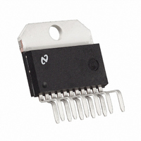
IC AMP AUDIO PWR 56W AB TO220-11
Manufacturer
National Semiconductor
Series
Overture™r
Type
Class ABr
Datasheet
1.LM3875TFNOPB.pdf
(20 pages)
Specifications of LM3875T
Output Type
1-Channel (Mono)
Max Output Power X Channels @ Load
56W x 1 @ 8 Ohm
Voltage - Supply
20 V ~ 84 V, ±10 V ~ 42 V
Features
Short-Circuit and Thermal Protection
Mounting Type
Through Hole
Package / Case
TO-220-11 (Bent and Staggered Leads)
Lead Free Status / RoHS Status
Lead free / RoHS Compliant
Other names
*LM3875T
*LM3875T/NOPB
LM3875T/NOPB
*LM3875T/NOPB
LM3875T/NOPB
Available stocks
Company
Part Number
Manufacturer
Quantity
Price

Part Number:
LM3875T
Manufacturer:
NS/国半
Quantity:
20 000
Company:
Part Number:
LM3875TF/NOPB
Manufacturer:
ABB
Quantity:
12


Definition of Terms
Input Offset Voltage: The absolute value of the voltage
which must be applied between the input terminals through
two equal resistances to obtain zero output voltage and
current.
Input Bias Current: The absolute value of the average of
the two input currents with the output voltage and current at
zero.
Input Offset Current: The absolute value of the difference
in the two input currents with the output voltage and current
at zero.
Input Common-Mode Voltage Range (or Input Voltage
Range): The range of voltages on the input terminals for
which the amplifier is operational. Note that the specifica-
tions are not guaranteed over the full common-mode voltage
range unless specifically stated.
Common-Mode Rejection: The ratio of the input common-
mode voltage range to the peak-to-peak change in input
offset voltage over this range.
Power Supply Rejection: The ratio of the change in input
offset voltage to the change in power supply voltages pro-
ducing it.
Quiescent Supply Current: The current required from the
power supply to operate the amplifier with no load and the
output voltage and current at zero.
Slew Rate: The internally limited rate of change in output
voltage with a large amplitude step function applied to the
input.
Class B Amplifier: The most common type of audio power
amplifier that consists of two output devices each of which
conducts for 180˚ of the input cycle. The LM3875 is a
Quasi-AB type amplifier.
Crossover Distortion: Distortion caused in the output stage
of a class B amplifier. It can result from inadequate bias
current providing a dead zone where the output does not
respond to the input as the input cycle goes through its zero
crossing point. Also for ICs an inadequate frequency re-
sponse of the output PNP device can cause a turn-on delay
giving crossover distortion on the negative going transistion
through zero crossing at the higher audio frequencies.
THD + N: Total Harmonic Distortion plus Noise refers to the
measurement technique in which the fundamental compo-
nent is removed by a bandreject (notch) filter and all remain-
ing energy is measured including harmonics and noise.
Signal-to-Noise Ratio: The ratio of a system’s output signal
level to the system’s output noise level obtained in the
absence of a signal. The output reference signal is either
specified or measured at a specified distortion level.
Continuous Average Output Power: The minimum sine
wave continuous average power output in watts (or dBW)
that can be delivered into the rated load, over the rated
bandwidth, at the rated maximum total harmonic distortion.
Music Power: A measurement of the peak output power
capability of an amplifier with either a signal duration suffi-
ciently short that the amplifier power supply does not sag
during the measurement, or when high quality external
power supplies are used. This measurement (an IHF stan-
dard) assumes that with normal music program material the
amplifier power supplies will sag insignificantly.
Peak Power: Most commonly referred to as the power out-
put capability of an amplifier that can be delivered to the
load; specified by the part’s maximum voltage swing.
17
Headroom: The margin between an actual signal operating
level (usually the power rating of the amplifier with particular
supply voltages, a rated load value, and a rated THD + N
figure) and the level just before clipping distortion occurs,
expressed in decibels.
Large Signal Voltage Gain: The ratio of the output voltage
swing to the differential input voltage required to drive the
output from zero to either swing limit. The output swing limit
is the supply voltage less a specified quasi-saturation volt-
age. A pulse of short enough duration to minimize thermal
effects is used as a measurement signal.
Output-Current Limit: The output current with a fixed out-
put voltage and a large input overdrive. The limiting current
drops with time once SPiKe protection circuitry is activated.
Output Saturation Threshold (Clipping Point): The output
swing limit for a specified input drive beyond that required for
zero output. It is measured with respect to the supply to
which the output is swinging.
Output Resistance: The ratio of the change in output volt-
age to the change in output current with the output around
zero.
Power Dissipation Rating: The power that can be dissi-
pated for a specified time interval without activating the
protection circuitry. For time intervals in excess of 100 ms,
dissipation capability is determined by heat sinking of the IC
package rather than by the IC itself.
Thermal Resistance: The peak, junction-temperature rise,
per unit of internal power dissipation (units in ˚C/W), above
the case temperature as measured at the center of the
package bottom.
The DC thermal resistance applies when one output transis-
tor is operating continuously. The AC thermal resistance
applies with the output transistors conducting alternately at a
high enough frequency that the peak capability of neither
transistor is exceeded.
Power Bandwidth: The power bandwidth of an audio am-
plifier is the frequency range over which the amplifier voltage
gain does not fall below 0.707 of the flat band voltage gain
specified for a given load and output power.
Power bandwidth also can be measured by the frequencies
at which a specified level of distortion is obtained while the
amplifier delivers a power output 3 dB below the rated out-
put. For example, an amplifier rated at 60W with ≤0.25%
THD + N, would make its power bandwidth measured as the
difference between the upper and lower frequencies at which
0.25% distortion was obtained while the amplifier was deliv-
ering 30W.
Gain-Bandwidth Product: The Gain-Bandwidth Product is
a way of predicting the high-frequency usefulness of an op
amp. The Gain-Bandwidth Product is sometimes called the
unity-gain frequency or unity-gain cross frequency because
the open-loop gain characteristic passes through or crosses
unity gain at this frequency. Simply, we have the following
relationship:
Assuming that at unity-gain
then we have the following:
This says that once fu (GBWP) is known for an amplifier,
then the open-loop gain can be found at any frequency. This
(A
CL1
= 1 or 0 dB) fu = f
A
GBWP = A
CL1
x f
1
= A
CL2
CL2
x f
x f
1
2
= GBWP,
2
www.national.com
Related parts for LM3875T
Image
Part Number
Description
Manufacturer
Datasheet
Request
R

Part Number:
Description:
LM387/LM387A Low Noise Dual Preamplifier
Manufacturer:
National Semiconductor
Datasheet:
Part Number:
Description:
LM387 - Low Noise Dual Preamplifier [Discontinued]
Manufacturer:
National Semiconductor
Part Number:
Description:
National Semiconductor [8-Bit D/A Converter]
Manufacturer:
National Semiconductor
Datasheet:
Part Number:
Description:
National Semiconductor [Media Coprocessor]
Manufacturer:
National Semiconductor
Datasheet:
Part Number:
Description:
Digitally Controlled Tone and Volume Circuit with Stereo Audio Power Amplifier, Microphone Preamp Stage and National 3D Sound
Manufacturer:
National Semiconductor
Datasheet:
Part Number:
Description:
Digitally Controlled Tone and Volume Circuit with Stereo Audio Power Amplifier, Microphone Preamp Stage and National 3D Sound
Manufacturer:
National Semiconductor
Datasheet:
Part Number:
Description:
AC97 Rev 2 Codec with Sample Rate Conversion and National 3D Sound
Manufacturer:
National Semiconductor
Part Number:
Description:
Manufacturer:
National Semiconductor
Datasheet:
Part Number:
Description:
Manufacturer:
National Semiconductor
Datasheet:
Part Number:
Description:
General Purpose, Low Voltage, Low Power, Rail-to-Rail Output Operational Amplifiers
Manufacturer:
National Semiconductor
Datasheet:
Part Number:
Description:
8-bit 20 MSPS flash A/D converter.
Manufacturer:
National Semiconductor
Datasheet:
Part Number:
Description:
Low Noise Quad Operational Amplifier
Manufacturer:
National Semiconductor
Datasheet:
Part Number:
Description:
Quad Differential Line Receivers
Manufacturer:
National Semiconductor
Datasheet:
Part Number:
Description:
Quad High Speed Trapezoidal? Bus Transceiver
Manufacturer:
National Semiconductor
Datasheet: