LM3875T National Semiconductor, LM3875T Datasheet - Page 16
LM3875T
Manufacturer Part Number
LM3875T
Description
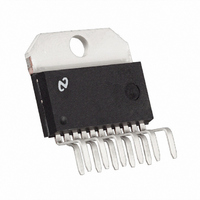
IC AMP AUDIO PWR 56W AB TO220-11
Manufacturer
National Semiconductor
Series
Overture™r
Type
Class ABr
Datasheet
1.LM3875TFNOPB.pdf
(20 pages)
Specifications of LM3875T
Output Type
1-Channel (Mono)
Max Output Power X Channels @ Load
56W x 1 @ 8 Ohm
Voltage - Supply
20 V ~ 84 V, ±10 V ~ 42 V
Features
Short-Circuit and Thermal Protection
Mounting Type
Through Hole
Package / Case
TO-220-11 (Bent and Staggered Leads)
Lead Free Status / RoHS Status
Lead free / RoHS Compliant
Other names
*LM3875T
*LM3875T/NOPB
LM3875T/NOPB
*LM3875T/NOPB
LM3875T/NOPB
Available stocks
Company
Part Number
Manufacturer
Quantity
Price

Part Number:
LM3875T
Manufacturer:
NS/国半
Quantity:
20 000
Company:
Part Number:
LM3875TF/NOPB
Manufacturer:
ABB
Quantity:
12


www.national.com
Application Information
resistance, the square wave response will exhibit ringing if
the capacitance is greater than about 0.2 µF. If highly ca-
pacitive loads are expected due to long speaker cables, a
method commonly employed to protect amplifiers from low
impedances at high frequencies is to couple to the load
through a 10Ω resistor in parallel with a 0.7 µH inductor. The
inductor-resistor combination as shown in the Typical Ap-
plication Circuit isolates the feedback amplifier from the
load by providing high output impedance at high frequencies
thus allowing the 10Ω resistor to decouple the capacitive
load and reduce the Q of the series resonant circuit. The LR
combination also provides low output impedance at low
frequencies thus shorting out the 10Ω resistor and allowing
the amplifier to drive the series RC load (large capacitive
load due to long speaker cables) directly.
GENERALIZED AUDIO POWER AMPLIFIER DESIGN
The system designer usually knows some of the following
parameters when starting an audio amplifier design:
The power output and load impedance determine the power
supply requirements, however, depending upon the applica-
tion some system designers may be limited to certain maxi-
mum supply voltages. If the designer does have a power
supply limitation, he should choose a practical load imped-
ance which would allow the amplifier to provide the desired
output power, keeping in mind the current limiting capabili-
ties of the device. In any case, the output signal swing and
current are found from (where P
power):
To determine the maximum supply voltage the following
parameters must be considered. Add the dropout voltage
(5 volts for LM3875) to the peak output swing, V
the supply rail value, (i.e. + V
I
voltage, usually about 15% higher. Supply voltage will also
rise 10% during high line conditions. Therefore, the maxi-
mum supply voltage is obtained from the following equation:
The input sensitivity and the output power specs determine
the minimum required gain as depicted below:
Normally the gain is set between 20 and 200; for a 40W, 8Ω
audio amplifier this results in a sensitivity of 894 mV and
89 mV, respectively. Although higher gain amplifiers provide
greater output power and dynamic headroom capabilities,
there are certain shortcomings that go along with the so
called “gain”. The input referred noise floor is increased and
hence the SNR is worse. With the increase in gain, there is
also a reduction of the power bandwidth which results in a
decrease in feedback thus not allowing the amplifier to re-
opeak
max. supplies ≈
Desired Power Output
Input Impedance
Maximum Supply Voltage
). The regulation of the supply determines the unloaded
±
(V
opeak
+ Vod(1 + regulation)(1.1) (7)
opeak
O
+ Vod) at a current of
is the average output
Load Impedance
(Continued)
Input Level
Bandwidth
opeak
, to get
(5)
(6)
(8)
16
spond as quickly to nonlinearities. This decreased ability to
respond to nonlinearities increases the THD + N specifica-
tion.
The desired input impedance is set by R
can cause board layout problems and DC offsets at the
output. The value for the feedback resistance, R
chosen to be a relatively large value (10 kΩ–100 kΩ), and
the other feedback resistance, Ri, is calculated using stan-
dard op amp configuration gain equations. Most audio am-
plifiers are designed from the non-inverting amplifier configu-
ration.
DESIGN A 40W/8Ω AUDIO AMPLIFIER
Given:
Equations (5), (6) give:
Therefore the supply required is:
With 15% regulation and high line the final supply voltage is
±
check the Power Output vs Supply Voltage to ensure that the
required output power is obtainable from the device while
maintaining low THD + N. It is also good to check the Power
Dissipation vs Supply Voltage to ensure that the device can
handle the internal power dissipation. At the same time
designing in a relatively practical sized heat sink with a low
thermal resistance is also important. Refer to Typical Per-
formance Characteristics graphs and the Thermal Con-
siderations section for more information.
The minimum gain from Equation (8) is: A
We select a gain of 21 (Non-Inverting Amplifier); resulting in
a sensitivity of 894 mV.
Letting R
ance, however, this would eliminate the “volume control”
unless an additional input impedance was placed in series
with the 10 kΩ potentiometer that is depicted in Figure 1.
Adding the additional 100 kΩ resistor would ensure the
minimum required input impedance.
For low DC offsets at the output we let R
for Ri (Non-Inverting Amplifier) gives the following:
The bandwidth requirement must be stated as a pole, i.e.,
the 3 dB frequency. Five times away from a pole give
0.17 dB down, which is better than the required 0.25 dB.
Therefore:
At this point, it is a good idea to ensure that the Gain
Bandwidth Product for the part will provide the designed gain
out to the upper 3 dB point of 100 kHz. This is why the
minimum GBWP of the LM3875 is important.
Solving for the low frequency roll-off capacitor, Ci, we have:
38.3V using Equation (7). At this point it is a good idea to
40W/8Ω
Ri = R
Power Output
Load Impedance
Input Level
Input Impedance
Bandwidth
GBWP = A
IN
f1
Ci
/(A
GBWP = 2.0 MHz (min) for LM3875
equal 100 kΩ gives the required input imped-
>
V
V
− 1) = 100k/(21 − 1) = 5 kΩ; use 5.1 kΩ
opeak
f
1/(2π Ri f
V
H
x f3 dB = 21 x 100 kHz = 2.1 MHz
= 20 kHz x 5 = 100 kHz
f
L
= 25.3V
= 20 Hz/5 = 4 Hz
L
) = 7.8 µF; use 10 µF.
20 Hz–20 kHz
±
I
opeak
30.3V
f1
IN
= 3.16A
@
. Very high values
= 100 kΩ. Solving
V
3.16A
≥ 18
f1
±
, should be
0.25 dB
100 kΩ
1V
40W
(max)
8Ω
Related parts for LM3875T
Image
Part Number
Description
Manufacturer
Datasheet
Request
R

Part Number:
Description:
LM387/LM387A Low Noise Dual Preamplifier
Manufacturer:
National Semiconductor
Datasheet:
Part Number:
Description:
LM387 - Low Noise Dual Preamplifier [Discontinued]
Manufacturer:
National Semiconductor
Part Number:
Description:
National Semiconductor [8-Bit D/A Converter]
Manufacturer:
National Semiconductor
Datasheet:
Part Number:
Description:
National Semiconductor [Media Coprocessor]
Manufacturer:
National Semiconductor
Datasheet:
Part Number:
Description:
Digitally Controlled Tone and Volume Circuit with Stereo Audio Power Amplifier, Microphone Preamp Stage and National 3D Sound
Manufacturer:
National Semiconductor
Datasheet:
Part Number:
Description:
Digitally Controlled Tone and Volume Circuit with Stereo Audio Power Amplifier, Microphone Preamp Stage and National 3D Sound
Manufacturer:
National Semiconductor
Datasheet:
Part Number:
Description:
AC97 Rev 2 Codec with Sample Rate Conversion and National 3D Sound
Manufacturer:
National Semiconductor
Part Number:
Description:
Manufacturer:
National Semiconductor
Datasheet:
Part Number:
Description:
Manufacturer:
National Semiconductor
Datasheet:
Part Number:
Description:
General Purpose, Low Voltage, Low Power, Rail-to-Rail Output Operational Amplifiers
Manufacturer:
National Semiconductor
Datasheet:
Part Number:
Description:
8-bit 20 MSPS flash A/D converter.
Manufacturer:
National Semiconductor
Datasheet:
Part Number:
Description:
Low Noise Quad Operational Amplifier
Manufacturer:
National Semiconductor
Datasheet:
Part Number:
Description:
Quad Differential Line Receivers
Manufacturer:
National Semiconductor
Datasheet:
Part Number:
Description:
Quad High Speed Trapezoidal? Bus Transceiver
Manufacturer:
National Semiconductor
Datasheet: