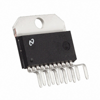
LM3875T National Semiconductor, LM3875T Datasheet - Page 15

LM3875T
Manufacturer Part Number
LM3875T
Description
IC AMP AUDIO PWR 56W AB TO220-11
Manufacturer
National Semiconductor
Series
Overture™r
Type
Class ABr
Datasheet
1.LM3875TFNOPB.pdf
(20 pages)
Specifications of LM3875T
Output Type
1-Channel (Mono)
Max Output Power X Channels @ Load
56W x 1 @ 8 Ohm
Voltage - Supply
20 V ~ 84 V, ±10 V ~ 42 V
Features
Short-Circuit and Thermal Protection
Mounting Type
Through Hole
Package / Case
TO-220-11 (Bent and Staggered Leads)
Lead Free Status / RoHS Status
Lead free / RoHS Compliant
Other names
*LM3875T
*LM3875T/NOPB
LM3875T/NOPB
*LM3875T/NOPB
LM3875T/NOPB
Available stocks
Company
Part Number
Manufacturer
Quantity
Price
Part Number:
LM3875T
Manufacturer:
NS/国半
Quantity:
20 000
Company:
Part Number:
LM3875TF/NOPB
Manufacturer:
ABB
Quantity:
12
Application Information
LAYOUT, GROUND LOOPS AND STABILITY
The LM3875 is designed to be stable when operated at a
closed-loop gain of 10 or greater, but as with any other
high-current amplifier, the LM3875 can be made to oscillate
under certain conditions. These usually involve printed cir-
cuit board layout or output/input coupling.
When designing a layout, it is important to return the load
ground, the output compensation ground, and the low level
(feedback and input) grounds to the circuit board common
ground point through separate paths. Otherwise, large cur-
rents flowing along a ground conductor will generate volt-
ages on the conductor which can effectively act as signals at
the input, resulting in high frequency oscillation or excessive
distortion. It is advisable to keep the output compensation
components and the 0.1 µF supply decoupling capacitors as
close as possible to the LM3875 to reduce the effects of PCB
trace resistance and inductance. For the same reason, the
ground return paths should be as short as possible.
In general, with fast, high-current circuitry, all sorts of prob-
lems can arise from improper grounding which again can be
avoided by returning all grounds separately to a common
point. Without isolating the ground signals and returning the
grounds to a common point, ground loops may occur.
“Ground Loop” is the term used to describe situations occur-
ring in ground systems where a difference in potential exists
between two ground points. Ideally a ground is a ground, but
unfortunately, in order for this to be true, ground conductors
with zero resistance are necessary. Since real world ground
leads possess finite resistance, currents running through
them will cause finite voltage drops to exist. If two ground
return lines tie into the same path at different points there will
be a voltage drop between them. The first figure below
shows a common ground example where the positive input
ground and the load ground are returned to the supply
ground point via the same wire. The addition of the finite wire
resistance, R
two points as shown below.
2
, results in a voltage difference between the
(Continued)
15
The load current I
I
phase. Therefore the voltage appearing at the non-inverting
input is effectively positive feedback and the circuit may
oscillate. If there were only one device to worry about then
the values of R
be ignored; however, several devices normally comprise a
total system. Any ground return of a separate device, whose
output is in phase, can feedback in a similar manner and
cause instabilities. Out of phase ground loops also are
troublesome, causing unexpected gain and phase errors.
The solution to most ground loop problems is to always use
a single-point ground system, although this is sometimes
impractical. The third figure above is an example of a single-
point ground system.
The single-point ground concept should be applied rigor-
ously to all components and all circuits when possible. Vio-
lations of single-point grounding are most common among
printed circuit board designs, since the circuit is surrounded
by large ground areas which invite the temptation to run a
device to the closest ground spot. As a final rule, make all
ground returns low resistance and low inductance by using
large wire and wide traces.
Occasionally, current in the output leads (which function as
antennas) can be coupled through the air to the amplifier
input, resulting in high-frequency oscillation. This normally
happens when the source impedance is high or the input
leads are long. The problem can be eliminated by placing a
small capacitor, C
the LM3875 input terminals. Refer to the External Compo-
nents Description section relating to component interaction
with C
REACTIVE LOADING
It is hard for most power amplifiers to drive highly capacitive
loads very effectively and normally results in oscillations or
ringing on the square wave response. If the output of the
LM3875 is connected directly to a capacitor with no series
1
, thus V
f
.
1
will follow the output voltage directly, i.e., in
1
and R
L
C
will be much larger than input bias current
, (on the order of 50 pF–500 pF) across
2
would probably be small enough to
01144913
www.national.com


