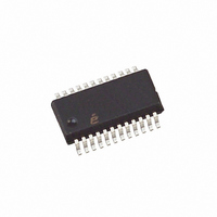
EL4543IUZ Intersil, EL4543IUZ Datasheet - Page 15

EL4543IUZ
Manufacturer Part Number
EL4543IUZ
Description
IC DVR TRPL DIFF TW-PAIR 24-QSOP
Manufacturer
Intersil
Specifications of EL4543IUZ
Applications
Driver
Output Type
Differential
Number Of Circuits
3
-3db Bandwidth
350MHz
Slew Rate
1000 V/µs
Current - Supply
14.5mA
Current - Output / Channel
60mA
Voltage - Supply, Single/dual (±)
5 V ~ 12 V, ±2.5 V ~ 6 V
Mounting Type
Surface Mount
Package / Case
24-QSOP
Device Type
Differential Line
Supply Voltage Range
5V To 12V
Driver Case Style
QSOP
No. Of Pins
24
Operating Temperature Range
-40°C To +85°C
Msl
MSL 2 - 1 Year
Filter Terminals
SMD
Rohs Compliant
Yes
Lead Free Status / RoHS Status
Lead free / RoHS Compliant
Available stocks
Company
Part Number
Manufacturer
Quantity
Price
Company:
Part Number:
EL4543IUZ
Manufacturer:
Intersil
Quantity:
12 045
Part Number:
EL4543IUZ
Manufacturer:
INTERSIL
Quantity:
20 000
Company:
Part Number:
EL4543IUZ-T
Manufacturer:
INTERSIL
Quantity:
6
Part Number:
EL4543IUZ-T
Manufacturer:
INTERSIL
Quantity:
20 000
Company:
Part Number:
EL4543IUZ-T13
Manufacturer:
INTERSIL
Quantity:
4 500
Part Number:
EL4543IUZ-T13
Manufacturer:
INTERSIL
Quantity:
20 000
Company:
Part Number:
EL4543IUZ-T7
Manufacturer:
INTERSIL
Quantity:
9 000
Part Number:
EL4543IUZ-T7
Manufacturer:
INTERSIL
Quantity:
20 000
EL4543/EL5375/EL8201 CAT5 RGB + Sync
Video Transmission System
Introducing a low cost turn-key system for transmitting
component video over short to moderate CAT5 cable lengths
(1 to 500 feet) with selectable cable loss and skew
compensation. Using only 3 of the 4 pairs in standard CAT5
the 4
transmission; an additional benefit.
RGB video plus sync (5 channels) is received at the VGA
terminal and presented single ended to the EL4543. The
EL4543 converts single ended RGB into fully differential
signals on three twisted pairs. Sync is encoded on the three
RGB differential signals as differential common mode and
then drives the differential signals with encoded sync
through CAT5 cable. The common mode of the signals is
extracted from the differential signals with a passive network
of resistors and passed to the EL8201 for sync decoding.
The differential signal is passed directly to the EL5375 where
it is amplified, converted back into single ended format.
Signal attenuation occurs in all transmission lines as a
function of increasing cable length; this application system
utilizes individual channel 2-pole compensation for cable
lengths of 150, 300 and 500 feet. Additionally, the
compensation network can be manipulated to provide some
th
pair is available for audio, function control or data
15
EL4543
measure of cable prop delay skew compensation for slight
differences in cable lengths between CAT5 pairs. Cable
skew can best be done around the 300ft range by under
compensating the shortest color pair (color on the left side of
a vertical line) and over compensate the longest color pair
(color on the right side of a vertical line). Around 450ft only
the shortest color pair can be under compensated.
The board for the driver and receiver should use strip lines
or strip line waveguides for the inputs and outputs of the
drivers and receivers. The 75Ω input and output strip lines
waveguide on 0.06 inch epoxy board with ground back plain
should be 0.016 inch wide with 0.01 inch space to ground
area around them. The differential pair strip line waveguides
should be two 0.045 inch 50Ω lines spaced 0.01 inch apart
and spaced 0.01 inch to ground area around them. This is a
general guide and size values may very for many reasons.
The receiver feedback and gain resistor network which goes
directly to the minus input should be connected very close
with minimal trace length and minimal capacitance to
ground. The ground plane on the backside of the board, in
back of these resistors and the minus input pin should be
removed as well.
September 13, 2007
FN7325.11


